7
3-90-08101R23_06/13
Assembly
Blower Assembly
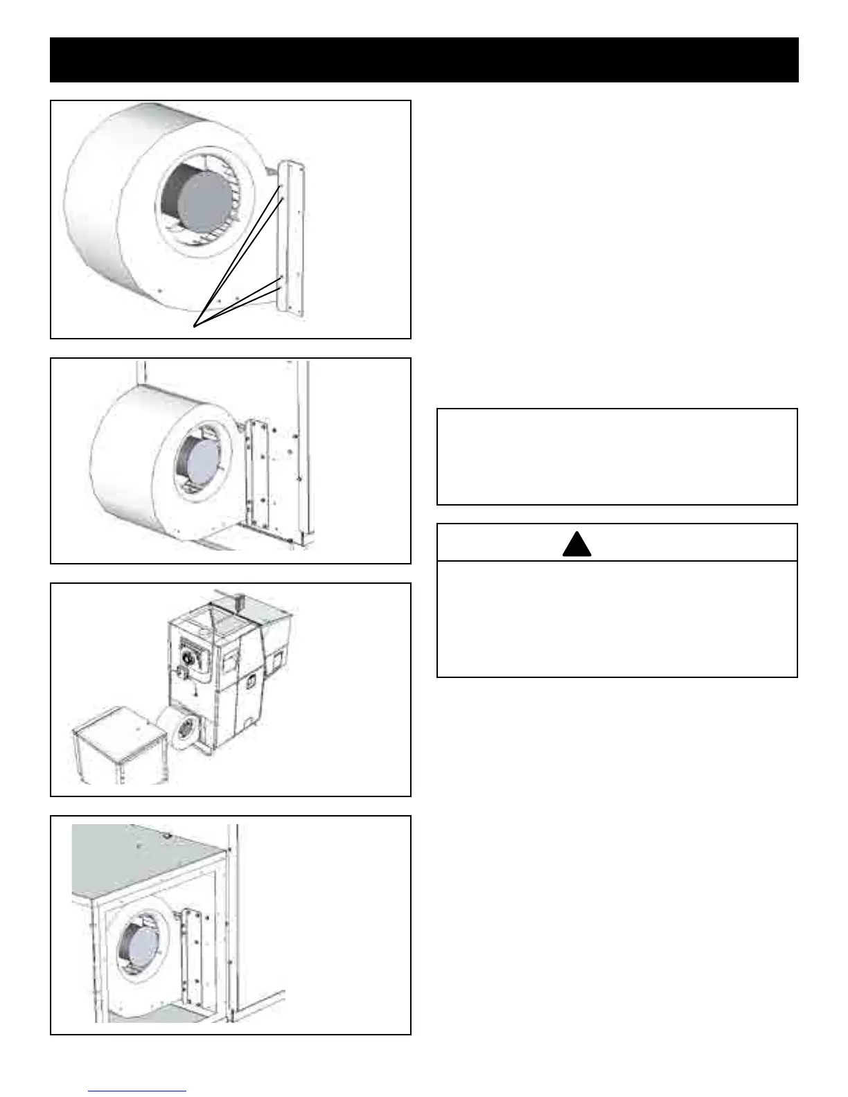
Installtheblowermountingbracketsontheblowerasshown
inFig.11.
1. Install(4)TekscrewsoneachsidewhereshowninFig.
11.Startwiththetwocenterscrews.
NOTE:Therearetwosmallholesinthedischargeendofthe
blowerthatmatchthetwocenterholesonthesmallangle
oftheblowerbracket.Thetwo(2)outerholesaredrilledby
theTekscrews.
2. Mountblowerwithbracketsinstalledonthefurnaceas
showninFig.12.Eachsidewillrequire6Tekscrews.
NOTE: Thefurnacebloweropeningismadelargeenoughfor
theuseofanyofthe3offeredblowers.Theblowermounting
bracketswillteitherblower.Theinnerholepatternisfor
the1000CFMblowerandtheouterpatternisforthe1450
or1638CFMblowers.
Regardless of the supply air duct size installed, the
DistributionBlowerMotorMUSTbecheckedforrunning
Amperage. Check the motor name plate for the full
loadAMPS.Iftheamperageisrunninghigherthanthat
listed,asupplyairrestrictingdampermayberequired
toincreasethesupplyplenumpositivestaticpressure.
Mounting Screws
Fig. 11
Fig. 12
Fig. 13
Fig. 14
NOTE: These Blower Motors are not designed to be
operated without any positive static back pressure.
OPERATION WITHOUT SUPPLY DUCTWORK OR IN
FREE AIR WILL CAUSE MOTOR OVERLOAD AND
PREMATURE FAILURE.
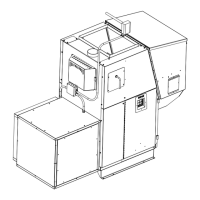
3. Mountthelterboxonthefurnacewith(6)#10x3/4Tek
screws,3on eachside. Visuallylocate theseholes so
youarefamiliarwiththeirlocationonthelterboxand
thefurnace.Accesstothemountingholescanbegained
through the blower access panel cover and the lter
opening.SeeFig.14.
Note: Twopiecesof2x4stackedlayingatontheoor12
inches from the blower opening will support the lter box
duringinstallation
CAUTION