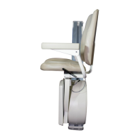
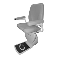
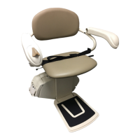
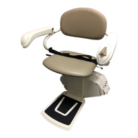
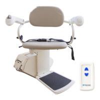
Helix Curved Stair Lift - Install and Service Manual 2016
15
TEC0067 P/N: 630-00063-01 Rev B
TECHNICAL SPECIFICATIONS
Technical Specications
Weight capacity: .............................................................350 lbs.
Track (rail) Type: ................................................Steel, Powder Coated
Travel: ..................................................20’ Standard; 164’ Maximum
Average Number of Return Trips per Charge
(varies with load, length): ..........................................................10
Symmetrical Lift
(Ships and installs non-handed): .................................................. No
Control in Armrest:
(left or right hand operation) .....................................................Yes
Lift Mounts to Steps or Wall: ....................................................Steps
Minimum Folded Width: .............................................14.37” (365 mm)
Minimum Footrest Height: ............................................5 ½” (140 mm)
Clear Distance
Between Armrests: ...................................... 20.47”- 23.6” (520 - 600 mm)
Floor to Seat Height: ...................................................24” (610 mm)
Minimum Wall to Stair Side of Rail: ..................................... 4.7” (120 mm)
Seat Depth: .........................................................14.96” (380 mm)
Backrest Height From Top of Seat: ...................................20.47” (520 mm)
Electrical Requirements: .............................. 120VAC 15A (240 VAC optional)
Operation Power: ....................................................24V DC Battery
Speed: .......................................................................20 fpm
Incline Range: (max. 450 by code): ................................................60˚
Drive System: .................................................... Rack & Pinion Gear
Safety Features: .............................................Direction Limit Switches
. . . . . . . . . . . . . . . . . . . . . . . . . . . . . . . . . . . . . . . . . . . . . . . . . . . . . . . . . . . . . . . . . . . .Final Limit Switch
. . . . . . . . . . . . . . . . . . . . . . . . . . . . . . . . . . . . . . . . . . . . . . . . . . . . . . . . . Footrest Obstruction Switch
. . . . . . . . . . . . . . . . . . . . . . . . . . . . . . . . . . . . . . . . . . . . . . . . . . . . . . . . . . . Seat Swivel/Cut-o Switch
. . . . . . . . . . . . . . . . . . . . . . . . . . . . . . . . . . . . . . . . . . . . . . . . . . . . . . . . . . Constant Pressure Controls
. . . . . . . . . . . . . . . . . . . . . . . . . . . . . . . . . . . . . . . . . . . . . . . . . . . . . . . . . . . . . . . . . . . . . . . . . . . . Seat Belt
. . . . . . . . . . . . . . . . . . . . . . . . . . . . . . . . . . . . . . . . . . . . . . . . . . . Safety Edges Overspeed Governor
. . . . . . . . . . . . . . . . . . . . . . . . . . . . . . . . . . . . . . . . . . . . . . . . . . . . . . . . . . . . . . . . . . . . .Emergency Stop
Safety Design Standards: .................................Complies with ASME A18.1,
CAN/CSA B44.1, ASME A17.5
Warranty: .................................................... 2-Year on Components
*Note: Average incline must not exceed 45° per ASME A18.1.
*


 To Next Page