17
Chapter 1 Overview of the FHA-C series
GND
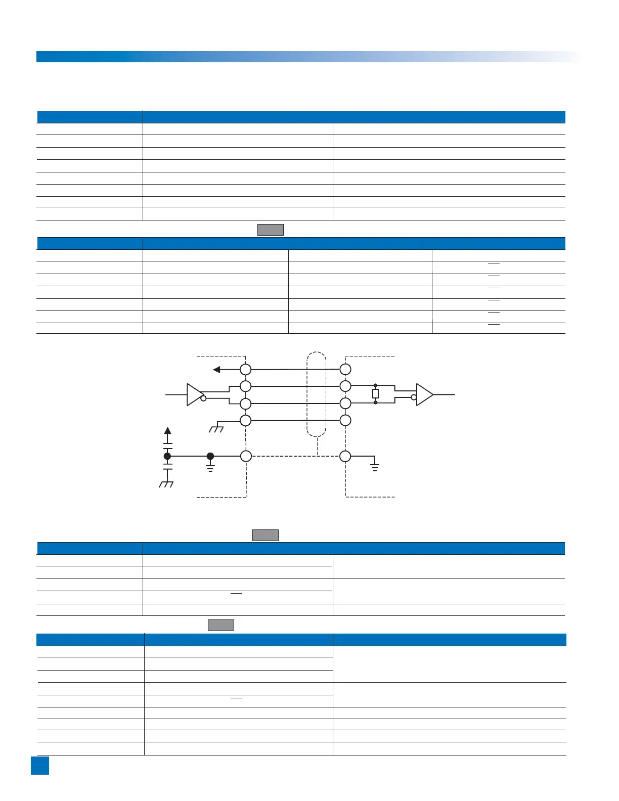
M26LS31C (Equivalent)
CC
,B,Z,U,V,W
_
A,
_
B,
_
Z,
_
U,
_
V,
_
W
AM26LS32C
(Equivalent)
Output circuit Input circuit of user’s device (Ex.)
CC
GND
Voltage strength of capacitor C1,C2 : 50V
FG
FG
C1
C2
R1
R1:120_
1-14 Cable specifications
The following tables show the lead specifications for the motors and the encoders of the FHA-C actuators.
• Motor Cable
Color Motor specification
Standard Brake option
Red Motor phase-U Motor phase-U
White Motor phase-V Motor phase-V
Black Motor phase-W Motor phase-W
Green/yellow PE PE
Blue No connection Brake
Yellow No connection Brake
(Shield) FG FG
• Encoder Lead for 14 Wire Incremental Encoder INC
Color Signal Color Signal
Red Vcc Black GND
Green A Green/White A
Gray B Gray/White
B
Yellow Z Yellow/White
Z
Brown U Brown/White
U
Blue V Blue/White
V
Orange W Orange/White
W
• Encoder Lead for 4 Wire Incremental Encoder INC
Color Signal Reference
Red +5V Power
Black 0V
Supply
Yellow SD Serial Signal
Blue
SD
Differential Output
(Shield) FG
• Encoder Lead for Absolute Encoder ABS
Color Signal Reference
Red +5V
Black 0V Power Supply
White 0V
Yellow SD Serial Signal
Blue
SD
Differential Output
Orange BAT+ Battery+
Gray BAT- Battery-
Green CLR Clear Signal
(Shield) FG
 Loading...