Harmonic Drive LLC 800-921-3332
18
Chapter 1 Overview of the FHA-C series
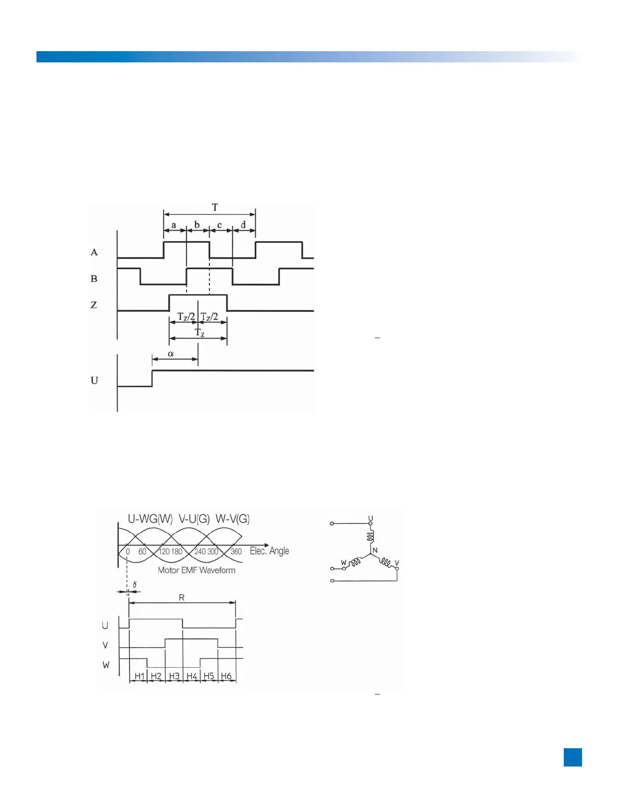
1-15 Signal Waveform
Signal waveform specifications of new version FHA-17C / 25C / 32C / 40C for US market
Figure 1 shows A, B and Z signal and relationship with U signal with CW rotation
facing the encoder end (the end of the actuator output shaft.)
Figure 1
a, b, c, d = 1/4T ± 1/10T
(a + b), (b+c) = 1/2T ± 1/8T
Tz = 1/2T ~ 3/2T
(The Z phase includes a HIGH state
in case of both of A and B phase is
HIGH state.)
T = 360º / 2500
a < ± 10º (Mechanical angle)
Figure 2shows U, V, and W signal and relationship[ with motor’s EMF with CW rotation
facing the encoder end (the end of the actuator output shaft.)
Figure 2
Voltage of U-W (G) means of voltage
of U terminal grounding W terminal.
R = 60º ± 3º
Hn = 10º ± 3º (Mechanical angle)
a < ± 10º / 6 (Mechanical angle)
Encoder Output
 Loading...