Revision A • 6/06
HARRIS CORPORATION
1-4
1 Introducing NetWave
CAT-5 cable. Since each DSP & I/O card carries
eight audio channels, up to four Dual Fader pan-
els are plugged into each DSP & I/O card.
Each Dual Fader channel control strip has two
audio inputs and one logic I/O connector associ-
ated with it on the DSP & I/O card. Since each
channel strip has two possible sources (A and B),
which audio input is used for each source is as-
signed during console setup. In the standard, non-
linked, NetWave console the two possible inputs
are the local analog input or the local digital in-
put assigned to that channel on the DSP & I/O
card. When the NetWave is linked to a VistaMax
system, there are three selections per source: the
local analog input, the local digital input, or a
routed VistaMax source.
The operating parameters for each source, on
each channel, are independently set during con-
sole setup through a common group of setup but-
tons and LEDs on each DSP & I/O card (shown
in the illustration on the previous page). These
controls set the parameters used when the A and
the B source is selected. The parameters include:
input type (is the input a control room mic, a stu-
dio mic, a line input or a Telco input?); whether
logic is be associated with that input; whether the
event timer is reset at channel on; whether fader
start is active; etc. The parameter settings are
stored in nonvolatile RAM.
The channel strip’s A and B select buttons are
used along with the Take button to choose the
active source for that channel. When the A source
is active, yellow LEDs backlight the A source la-
bel under a smoked polycarbonate window above
the A button, and the A button is lit. When the B
source is active, red LEDs backlight the B source
label above the fader and the B button is lit.
Setting a channel source to use the logic I/O
means the channel can remotely control a periph-
eral device (mic control panel, CD player, com-
puter playback system, etc.) and that peripheral
can also control the channel. The logic I/O pro-
vides fully independent parallel logic functions
that: outputs start and stop pulses to line devices
(on and off tallies to mic panels); receives channel
on, off, cue and reset/ready commands from line
devices (on, off, cough and talkback commands
from mic panels).
Dual Router Channels
The optional Dual Router Kit changes the A/B
selector buttons on both channels of any Dual
Fader panel into VistaMax source selector Up/
Down buttons. To use this functionality, the
console’s VistaMax Link must be active.
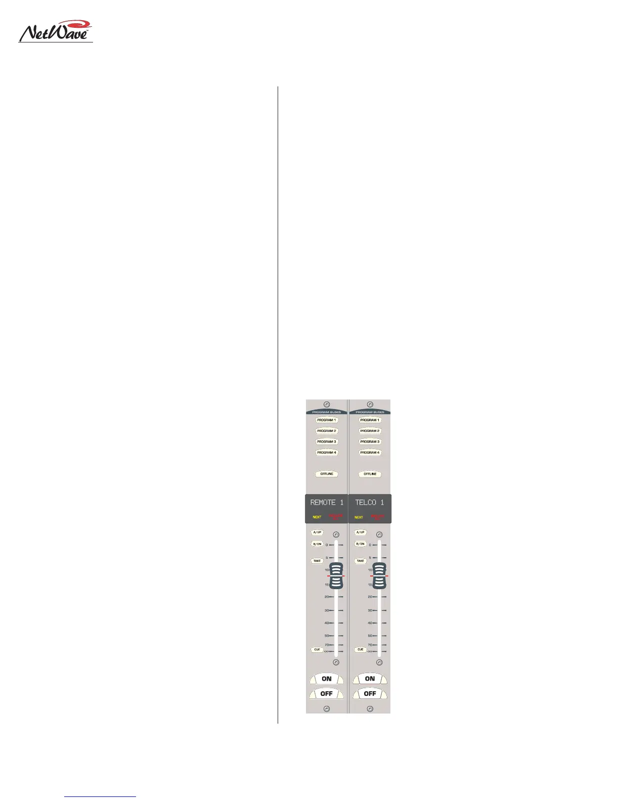
Dual Fader panels that have the Dual Router
Kit installed are easily identified by the two 10-
character signal name displays under the top half
of the smoked polycarbonate lens above the fader.
The display normally shows the name of the cur-
rent VistaMax source
feeding that channel.
But, when finding the
next source by pressing
an Up or Down button,
the displayed name
switches to show a po-
tential Next Source for
that channel. The yellow
Next label above the Up
button lights while the
Next Source name is dis-
played. Holding down, or
repeatedly tapping the
Up or Down button,
steps alphanumerically
through the list of poten-
tial Next Source names
available on that chan-
nel.
Once the desired
source name is shown,
Dual Router Panel