Revision A • 6/06
HARRIS CORPORATION
1-3
1 Introducing NetWave
» Separate control room and studio logic con-
nectors (warning interface output, logic I/O
for dim and mute control, talk logic output)
•DSP & I/O Cards:
» Sixteen stereo/dual mono audio inputs (eight
analog and eight digital), assignable as the A
or B source for the eight channel control strips
associated with that card
» Eight channel logic connectors, assignable to
either the A or B source for the eight channel
control strips associated with that card
•Other Connections:
» One 1/4" TRS jack for the board operator
headphones, left side panel
» One RJ-45 VistaMax Link connector for a
CAT-5e cable (requires the optional Link Ac-
tivation Kit be installed)
» One keyed connector for the 48-volt power
supply supplied with the console
» Four, eight or twelve internal RJ-45 sockets to
supply power and signals to the Dual Fader
panels
» Four, eight or twelve internal and rear panel
LAN passthru RJ-45 sockets for standard
CAT-5 cabling to connect the optional Dual
Router Kits to the VistaMax LAN
» One ESE or SMPTE master clock input on
the clock-timer board
» One Timer Reset output, for a studio event
timer, on the clock-timer board
MAIN COMPONENT DESCRIPTIONS
NetWave
board operators use three parts: the
Dual Fader panels; the Monitor panel; and the
Reflective Console Display. Each is covered in this
section along with descriptions for the other parts
making up the console: 48-volt power supplies,
the Monitor & Output card, the DSP & I/O card,
the VistaMax Link and the optional upgrade kits.
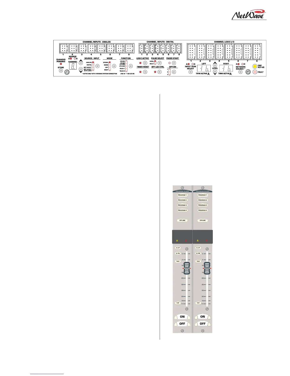
NetWave Dual Fader Panels
Each Dual Fader panel has two channel control
strips. Each strip has the following features: sepa-
rate channel on and off
buttons; a 100mm fader
for channel level control;
cue on/off button; A and
B source selector buttons
with a Take button; active
source illuminated label;
and five bus assignment
buttons (four Program
and one Offline).
Channel control is digi-
tal, so no audio ever trav-
els through the Dual
Fader panel. In fact, a
Dual Fader panel can be
swapped “hot” without af-
fecting either channel’s
audio performance.
Each Dual Fader panel
plugs into a DSP & I/O
card using a single red
Dual Fader Panel
DSP and I/O Card Connectors and Channel Setup Controls