Revision A • 6/06
HARRIS CORPORATION
2-9
2 Installation
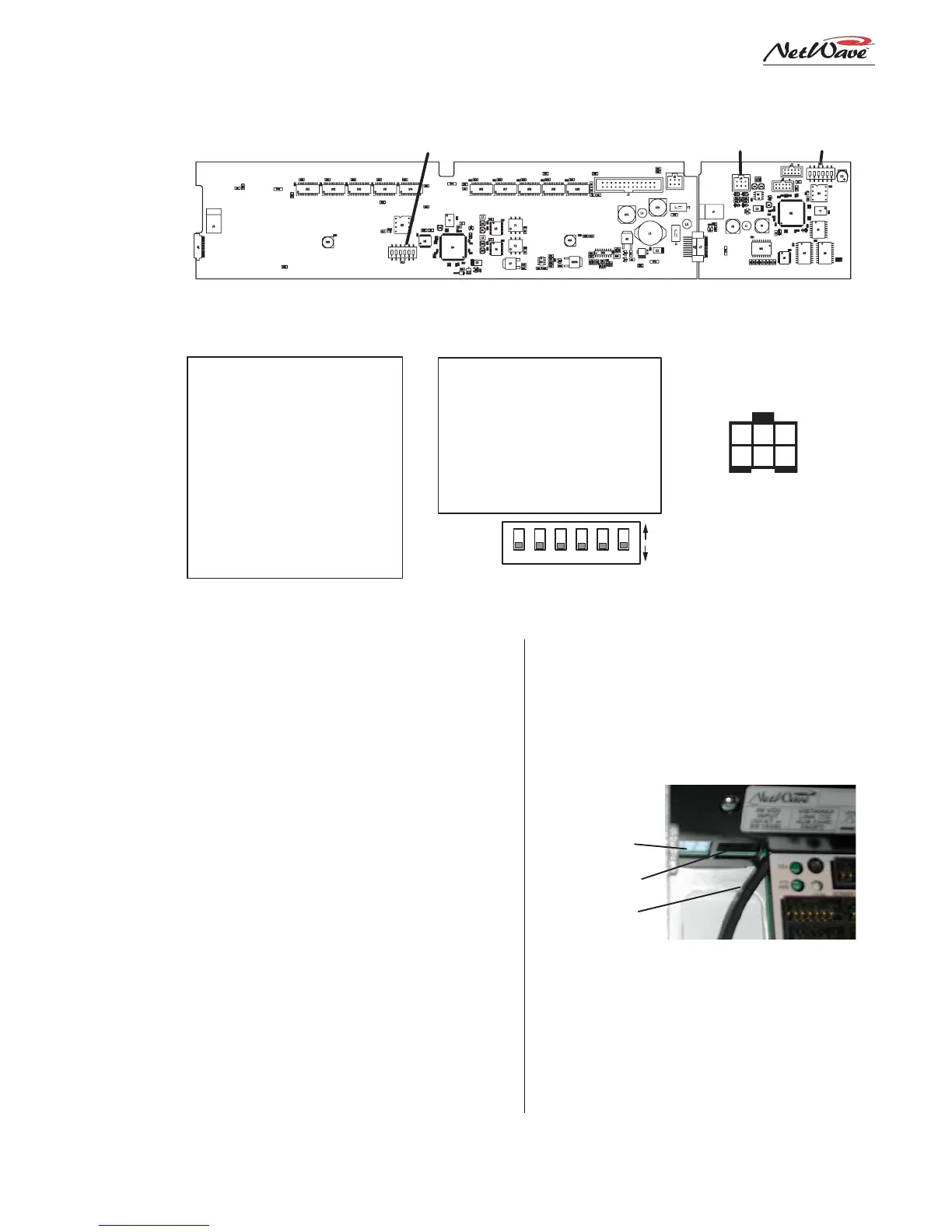
Clock Settings
Clock parameters are set using multi-switch
DS1, located near the upper right corner of the
clock-timer PCA. The default settings are all
switches set to off.
When used autonomously, the clock time can
display 12-hour or 24-hour time. Set DS1-4 to on
to display 24-hour time. This setting is ignored
when a master clock signal is used.
When an ESE TC-89 or TC-90 master clock is
used, set DS1-2 to on. The ESE signal type is auto-
detected. When a SMPTE master clock is used,
set DS1-5 to on. If both DS1-2 and DS1-5 are set
on, only SMPTE is valid. An ESE signal will be
ignored.
ESE, SMPTE & Remote Timer Reset
An ESE or SMPTE master clock signal con-
nects to J4, pins 5 and 6. The signal is polarity
sensitive, but can be balanced or unbalanced. Con-
nect the high (center conductor) or + signal to pin
5 and the low (shield) or - signal to pin 6.
J4, pins 3 and 4 are used to connect a cable
that can reset a studio event timer. Pin 3 is the
timer reset output (pulse low on timer reset) and
pin 4 is ground.
NOTE: The wiring to J4 must be routed through a
small chassis opening (next to the RJ-45 Link
connector) before being terminated into the 6-pin
MOD IV housing. Leave sufficient wire length to
plug in J4 while the display is face down over the
control panels.
DS1 / DS3:
Default
settings
are all off
ON
OFF
1 2 3 4 5 6
6 5 4
3 2 1
Clock-Timer J4
(ESE / SMPTE
MASTER CLOCK &
REMOTE TIMER )
Meter Boards
DS3 Switch Settings
1 - Av & peak / average only
2 - 2s peak hold / no hold
3 - Blue LEDs turn on level*
4 - Blue LEDs turn on level*
5 - NetWave / RMXdigital
6 - NetWave / non-mirrored
Switch Function: Off / On
* Blue Peak LEDs turn on at:
-6 dBFS, 3 and 4 are off
-4 dBFS, 3 is on and 4 is off
-2 dBFS, 3 is off and 4 is on
0 dBFS, 3 and 4 are on
1 - .1s displays / .1 off (Timer)
2 - no ESE / ESE master
3 - unused
4 - 12-hour / 24-hour **
5 - no SMPTE / SMPTE master
6 - NetWave / non-mirrored
Switch Function: Off / On
Clock-Timer Board
DS1 Switch Settings
DS3 J4 DS1
METER PCA CLOCK-TIMER PCA
1 - TIMER RESET LOGIC, IN
2 - GROUND
3 - TIMER RESET LOGIC, OUT
4 - GROUND
5 - ESE or SMPTE INPUT +
6 - ESE or SMPTE INPUT -
* active only when 2 and 5
are both set to off
Console Display PCA Setup Switches and Connections
(orientation shown while set onto the control panels)
J4 (ESE/SMPTE, studio event timer reset) Cable
DC Input
RJ-45 Link
Cable to J4