Revision A • 6/06
HARRIS CORPORATION
2-10
2 Installation
Event Timer Settings
The event timer displays time in minutes, sec-
onds and tenths of seconds. The only timer setting
(DS1-1) sets whether the tenths of seconds digit is
displayed while the event timer is running.
When set off (the factory default) the tenths are
always displayed. When DS1-1 is set on, the tenths
of seconds are not displayed while the timer is
running, but are displayed while the timer is
stopped or is being held.
Meter Settings
The PGM 1 and Aux meter parameters are set
using multi-switch DS3 (shown on page 2-9). The
Quad Meter Package adds a second meter board.
The left-hand board’s DS3 settings affect the first
pair of meters (PGM 1 and PGM 2) and the right-
hand meter board’s DS3 settings affect the PGM
3 and Aux meters. Typically the two meter boards
would be set to the same settings. The DS3 fac-
tory settings are all switches set to off.
To turn off the peak displays and to show only
the average meter levels, set DS3-1 to on.
To have the Peak indicators decay immediately,
switch DS3-2 to on.
To change the level where the Blue LEDs turn
on: set DS3-3 and DS3-4 to off to turn on the Blue
LEDs at -6 dBFS; set DS3-3 on and DS3-4 off to
turn on the Blue LEDs at -4 dBFS; set DS3-3 off
and DS3-4 to turn on the Blue LEDs at -2 dBFS.
DS3-5 and DS3-6 must be left set to off for Net-
Wave consoles.
MONITOR & OUTPUT BOARD SETTINGS
The Monitor & Output board has two multi-
switches to assign various parameters to the Moni-
tor & Output board outputs. The factory default
setting for all switches is off.
To access the switches, the Monitor panel must
be removed from the frame. Follow the directions
on page 2-4 to remove the panel.
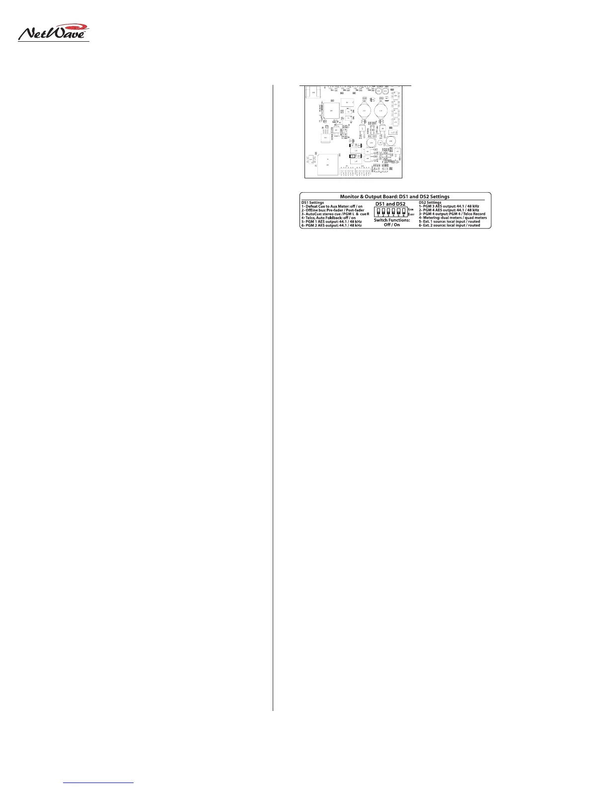
DS1 and DS2 Settings
Multi-switches DS1 and DS2 are at the front
edge of the Monitor & Output board, hidden be-
low the Monitor panel in normal use. Here is what
each switch does:
DS1-1 affects the Aux meter display. When off
the cue level is displayed while cue is active. When
set to on, the Aux meter does not display cue.
DS1-2 affects the Offline bus signals. When off,
Offline signals are derived pre-fader. When on, the
Offline signals are post-fader.
DS1-3 affects the operator headphone output
when AutoCue is active. When set off, cue is fed to
the headphones in stereo (typically used for pro-
duction rooms). When set to on, a split feed (moni-
tor to one ear, cue to the other ear) is sent to the
headphones (typically used for on-air consoles).
DS1-4 affects Telco channel operation. When set
to off, the mix-minus source (the winking bus as-
signment button) is not affected by turning the
Telco channel on or off. When set to on, the Auto
Foldback function is activated. The mix-minus out-
put automatically switches between Offline (Telco
channel off) and the lowest selected program bus
(Telco channel on). When Offline is not lit on the
Telco channel, no mix-minus audio is heard while
the channel is off, except for talkback to that Telco.
The next four switches (DS1-5, DS1-6, DS2-1
and DS2-2) set the sample rate outputs for the
Monitor & Output Board, Multi-Switch Settings
Exposed portion of
the Monitor & Output
board, below the
Monitor panel
DS1 DS2