Revision A • 6/06
HARRIS CORPORATION
2-22
2 Installation
tem (the NetWave is automatically synchronized
to the VistaMax system’s master clock, which can
be externally referenced). Refer to the VistaMax
(75-52) or Envoy (75-55) manuals for details.
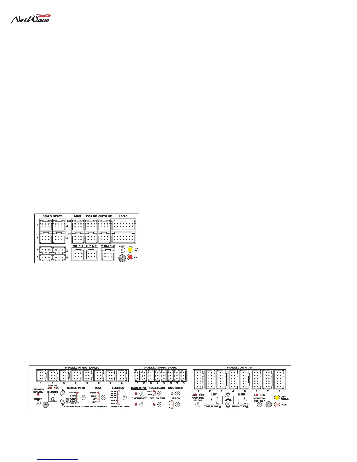
AUDIO CONNECTIONS
There are eighteen dedicated analog and digi-
tal inputs and outputs on the Monitor & Output
card. Connections include separate analog and
digital outputs for four Program buses (PGM 4
can alternately be set as a local Telco Record out-
put), analog inputs for two External Monitor sig-
nals, two analog mono mix-minus outputs, three
analog monitor outputs for the control room
(monitor, host headphone and guest headphone)
and three monitor outputs for a studio (monitor
host headphone and guest headphone).
Each DSP & I/O card has eight analog and eight
digital inputs that are assigned as sources using
the DSP & I/O setup controls. When the VistaMax
Link is activated, one input (either analog or digi-
tal) from each channel is set as a VistaMax source
that can be routed to any other VistaMax commu-
nity member. Likewise, each channel source can
be set to use a routed signal from the VistaMax
system as its input. See Chapter 4, VistaMax Sys-
tem, for details.
Any analog or digital input connector can be
set to function as two mono inputs rather than as
a combined stereo signal through the Mode selec-
tor setup control.
LOGIC CONNECTORS
The NetWave console has the following logic
connections:
• Channel Logic I/O (eight 12-pin MOD IV con-
nectors on each DSP & I/O card)
• Control Room Logic (14-pin MOD IV on the
Monitor & Output card) for warning light, ex-
ternal mute, dim, and talkback control
• Studio Logic (14-pin MOD IV on the Monitor
& Output card) for warning light, external
mute, dim, and talkback control
• Remote timer reset output and ESE or
SMPTE input on the clock-timer circuit board
in the Console Display assembly
Page 2-23 has block diagrams and pinouts for
the four types of NetWave logic interface connec-
tors.
The logic inputs are fully isolated by opto-cou-
plers and accept logic commands that use +5 to
+40 volt logic.
Logic outputs are solid-state “dry-contact relays.”
They can switch control signals of up to 60 volts,
AC or DC. They cannot directly control warning
lamps using 120 VAC. A warning lamp interface
must be used to connect the warning lamp.
(cont. page 2-24)
Monitor & Output Card
Connections
DSP & I/O Card Connections