Revision A • 6/06
HARRIS CORPORATION
2-23
2 Installation
14
9
8
5
12
4
Studio Warning Relay
Studio Warning Relay
Studio Dim Relay
Logic Ground
Logic Ground
Logic Ground
Relays Common
Studio Mute Relay
11
13
10
1
2
3
6
7
Internal Logic
Talk to Studio Relay
Logic Supply +5VDC
Logic Supply +5VDC
Studio Mute Input (-)
Studio Dim Input (-)
Enable Logic Inputs (+)
Notes:
Opto-Isolated inputs are current limited to work
with +5 to +40 VDC logic.
Opto-Isolated outputs can sink up to 60 volts or
350 mA max. current flow.
For fully isolated operation, do not connect external
devices to +5 or ground (pins 1, 2, 3, 6 and 7).
8 9 10 11 12 13 14
7 6 5 4 3 2 1
Wire insertion end view
1 - LOGIC GND
2 - LOGIC GND
3 - LOGIC GND
4 - WARNING RELAY
5 - WARNING RELAY
6 - +5 VOLT LOGIC SUPPLY
7 - +5 VOLT LOGIC SUPPLY
8 - MUTE STUDIO (-)
9 - DIM STUDIO (-)
10 - RELAYS COMMON
11 - MUTE RELAY
12 - DIM RELAY
13 - TALK TO STUDIO RELAY
14 - ENABLE LOGIC INPUTS (+)
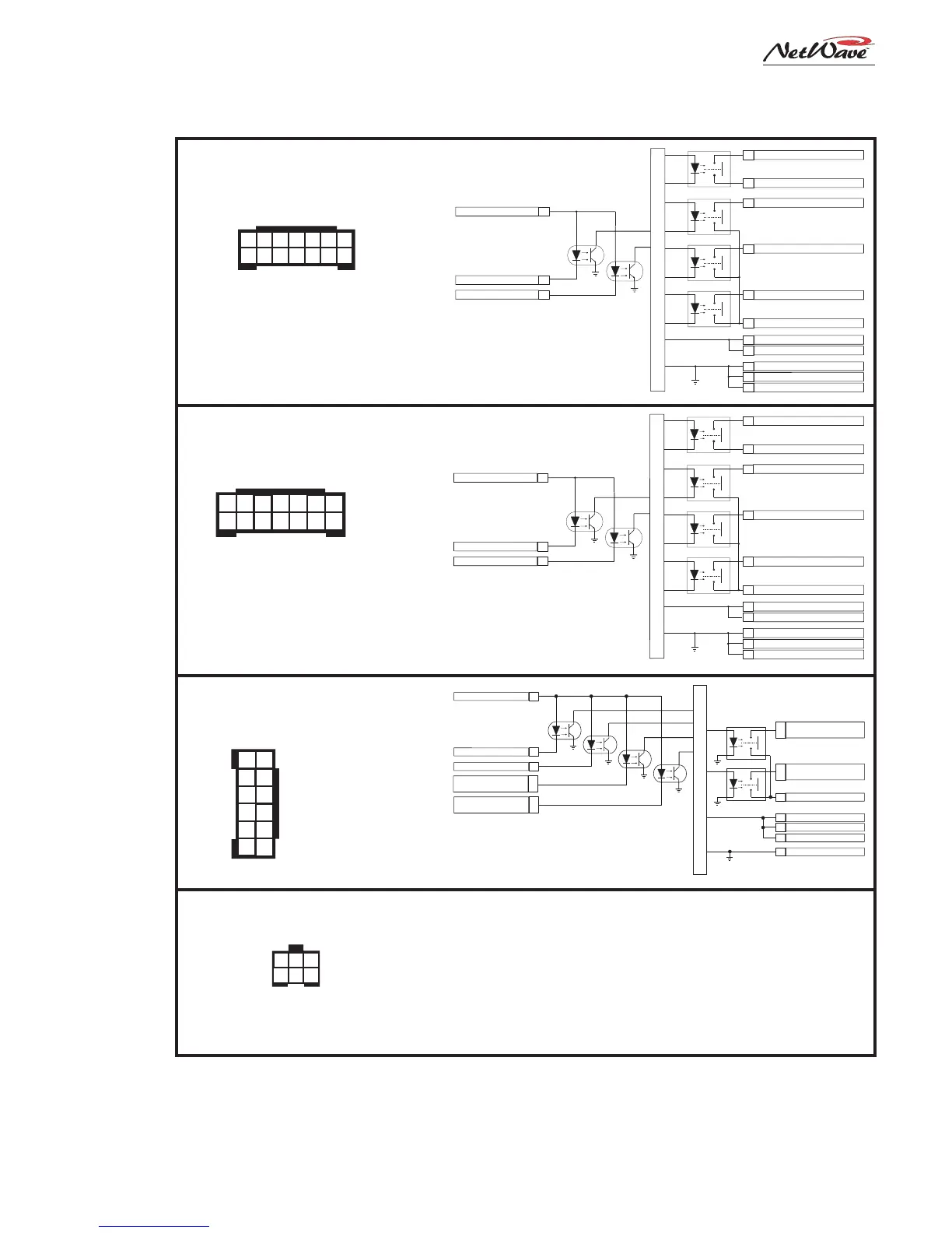
Studio Logic Interface,
Connector Pinout and Block Diagram
Channel Logic Interface,
Connector Pinout and
Block Diagram
4
2
9
3
11
MIC: On Tally Relay
LINE: Start Pulse Relay
Logic Ground
Tally & Pulse Common
6
1
12
10
7
Internal Logic
Logic Supply +5VDC
Logic Supply +5VDC
Logic Supply +5VDC
On (-)
Off (-)
MIC: Talk To C/R (-)
LINE: Cue (-)
Enable Logic Inputs (+)
Notes:
Opto-Isolated inputs are current limited to work
with +5 to +40 VDC logic.
Opto-Isolated outputs can sink up to 60 volts or
350 mA max. current flow.
For fully isolated operation, do not connect external
devices to +5 or ground (pins 1, 7, 10, and 12).
8
MIC: Cough (-)
LINE: Ready (-)
5
MIC: Off Tally Relay
LINE: Stop Pulse Relay
Wire insertion end view
1 - LOGIC GROUND
2 - TALK TO CR / CUE (-)
3 - CHANNEL OFF (-)
4 - ENABLE LOGIC INPUTS (+)
5 - OFF TALLY / STOP PULSE
6 - TALLY / PULSE COMMON
7 - +5 VOLT LOGIC SUPPLY
8 - COUGH / READY CTRL (-)
9 - CHANNEL ON (-)
10 - +5 VOLT LOGIC SUPPLY
11 - ON TALLY / START PULSE
12 - +5 VOLT LOGIC SUPPLY
6
5
4
3
2
1
12
11
10
9
8
7
14
9
8
5
12
4
Control Room Warning Relay
Control Room Warning Relay
Control Room Dim Relay
Logic Ground
Logic Ground
Logic Ground
Relays Common
Control Room Mute Relay
11
13
10
1
2
3
6
7
Internal Logic
Talk to Control Room Relay
Logic Supply +5VDC
Logic Supply +5VDC
Ctrl Room Mute Input (-)
Ctrl Room Dim Input (-)
Enable Logic Inputs (+)
Notes:
Opto-Isolated inputs are current limited to work
with +5 to +40 VDC logic.
Opto-Isolated outputs can sink up to 60 volts or
350 mA max. current flow.
For fully isolated operation, do not connect external
devices to +5 or ground (pins 1, 2, 3, 6 and 7).
Wire insertion end view
1 - LOGIC GND
2 - LOGIC GND
3 - LOGIC GND
4 - WARNING RELAY
5 - WARNING RELAY
6 - +5 VOLT LOGIC SUPPLY
7 - +5 VOLT LOGIC SUPPLY
8 - MUTE C/R (-)
9 - DIM C/R (-)
10 - RELAYS COMMON
11 - MUTE RELAY
12 - DIM RELAY
13 - TALK TO C/R RELAY
14 - ENABLE LOGIC INPUTS (+)
8 9 10 11 12 13 14
7 6 5 4 3 2 1
Control Room Logic Interface,
Connector Pinout and Block Diagram
6 5 4
3 2 1
Wire insertion end view
1 - EXT. TIMER RESET INPUT
2 - GROUND
3 - TIMER RESET OUTPUT
4 - GROUND
5 - ESE/SMPTE INPUT +
6 - ESE/EMPTE INPUT -
Clock-Timer Interface,
Connector Pinout and signals
NetWave Logic Connections on the Monitor & Output Card,
DSP & I/O Cards and Clock/Timer Circuit Board
Notes:
Pins 1 & 2. Typically not connected on a NetWave. This input resets
the timer when an active low command is received.
Pins 3 & 4. Connect to a Studio Timer's reset input. This active low
output resets the Studio Timer so it stays in sync with the console's timer.
Pins 5 & 6. Connects from a master clock. Any SMPTE, ESE TC-89 or
ESE TC-90 master clock can be used. On a balanced connection, connect
the high (+) signal to pin 5 and the low (-) to pin 6. There is no shield connection.
On an unbalanced signal, connect the center conductor to pin 5 and the
shield to pin 6.