Revision A • 6/06
HARRIS CORPORATION
2-28
2 Installation
BASIC PERIPHERAL DEVICE LOGIC CONNECTION EXAMPLE
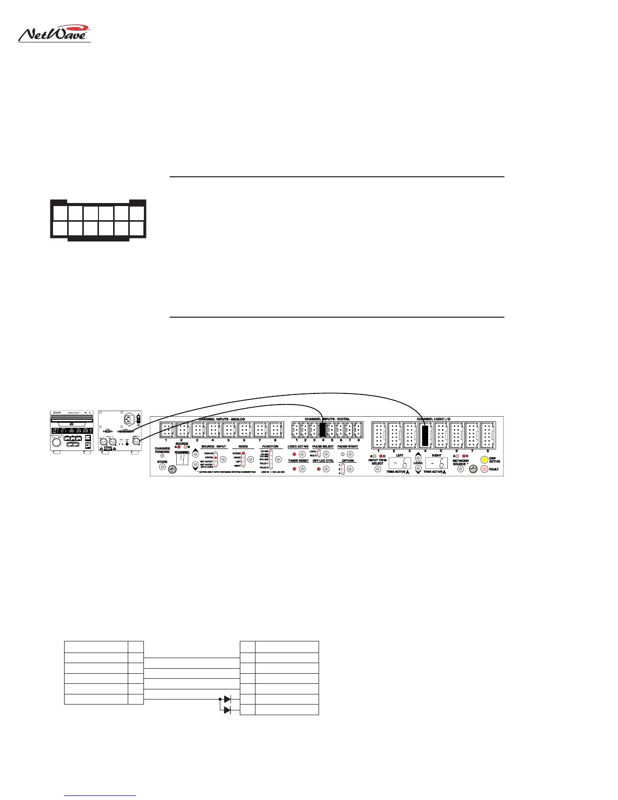
This example shows a peripheral device (with basic logic functions like the CD player shown below) connected
to an Channel Logic I/O connector.
CHANNEL LOGIC
CONNECTOR
DENON DN-SERIES
CD PLAYER LOGIC
SIGNAL PIN
PIN SIGNAL
BRN
BLK
GRN
RED
WHT
Pulse Common
Enable Logic Inputs (+)
Stop Pulse
Start Pulse
Ready (-)
6
4
5
11
8
23
22
3
2
16
15
Switch Common
Tally Common
Pause N.O.
Play N.O.
Standby/Cue Tally
Pause Tally
PARTS LIST
Cable: 19-119 (Belden 8445 or equiv.)
Diodes: 11-7 (1N4001 or equiv.)
25-pin DSub: 15-854 (DB-25P)
12-pin MOD IV housing: 14-490 (Tyco-AMP 87922-2)
MOD IV contacts: 15-938-1 (Tyco-AMP 102128-1)
CR1
CR2
PIN #PIN #
PIN #PIN #
PIN #
SIGNALSIGNAL
SIGNALSIGNAL
SIGNAL
FUNCTIONFUNCTION
FUNCTIONFUNCTION
FUNCTION
1 LOGIC GROUND Logic ground
2 CUE INPUT (-) Remote Cue switch input (active low)
3 OFF INPUT (-) Remote Off switch input (active low)
4
ENABLE LENABLE L
ENABLE LENABLE L
ENABLE L
OGIC INPUTOGIC INPUT
OGIC INPUTOGIC INPUT
OGIC INPUT
S (+)S (+)
S (+)S (+)
S (+) Jumper to +VDC to enable switch inputs
5
STST
STST
ST
OP PULSEOP PULSE
OP PULSEOP PULSE
OP PULSE Stop command output, N.O. contact
6
PULSE CPULSE C
PULSE CPULSE C
PULSE C
OMMONOMMON
OMMONOMMON
OMMON Start/Stop Pulse common, C contact
7 +5 VOLT LOGIC SUPPLY 5 volt source
8
READREAD
READREAD
READ
Y INPUT (-)Y INPUT (-)
Y INPUT (-)Y INPUT (-)
Y INPUT (-) Remote Ready switch input (active low)
9 ON INPUT (-) Remote On switch input (active low)
10 +5 VOLT LOGIC SUPPLY 5 volt source to enable switches
11
STST
STST
ST
ARAR
ARAR
AR
T PULSET PULSE
T PULSET PULSE
T PULSE Start command output, N.O. contact
12 +5 VOLT LOGIC SUPPLY 5 volt source for switch tallies
Notes: +VDC is between +5 and +40 VDC.
Outputs can switch voltages up to +60 VDC at 350 mA total
BB
BB
B
oldold
oldold
old indicates connections used in this example.
CHANNEL LOGIC I/O CONNECTOR SIGNAL TABLE
(wire insertion end view)
1 2 3 4 5 6
7 8 9 10 11 12
DSP & I/O Card
Denon CD Player,
connected to
channel 4, source A
To Logic I/O 4
To Digital Input 4
951
Channel 4 Parameter Settings (A source)
for a peripheral device using line logic
EXAMPLE OF CD PLAYER CONNECTED TO INPUT 4
1. Input: set to Digital
2. Mode: set to Stereo
3. Function: LINE (no LEDs lit)
4. Logic Active: On
5. Timer Reset: On
6. Remote Off LED Ctrl: On
(for Ready control of Off LED)
7. Input Trim: -6 dB on both channels
8. Network Source: set to Digital
(sets the CD player as a VistaMax source)
TYPICAL DENON CD PLAYER LOGIC WIRING