Revision A • 6/06
HARRIS CORPORATION
2-29
2 Installation
COMPLEX LOGIC CONNECTION EXAMPLE
This example shows a device with more complex logic functions like that typically found in a computer
playback system. On most peripheral devices, the logic ground and +5 volt supply connections are not used, but
in this example the playback system logic I/O connections are also isolated.
CHANNEL LOGIC
CONNECTOR
GPI 16 INTERFACE
CONNECTOR
SIGNAL PIN
PIN SIGNAL
BLK
WHT
BRN
RED
GRN
Start Pulse
Stop Pulse
On (-)
Ready (-)
Logic GND
Enable Logic Inputs (+)
+5 VDC
Pulse Common
+5 VDC
11
5
9
8
1
4
10
6
12
8
7
19
36
16
27
26
37
17
34
Input 0 (+)
Input 1 (+)
Relay 0 N.O.
Relay 1 N.O.
Relay 2 N.O.
Input 0 (-)
Input 1 (-)
Relay 0 common
Relay 1 Common
Relay 2 Common
CR1
CR2
PARTS LIST
Cable: 19-119 (Belden 8445 or equiv.)
Diodes: 11-7 (1N4001 or equiv.)
37-pin DSub: 15-885 (DC 110963-4)
DSub crimp pins: 15-884 (DB-37P)
12-pin MOD IV housing: 14-490 (Tyco-AMP 87922-2)
MOD IV contacts: 15-938-1 (Tyco-AMP 102128-1)
PIN #PIN #
PIN #PIN #
PIN #
SIGNALSIGNAL
SIGNALSIGNAL
SIGNAL
FUNCTIONFUNCTION
FUNCTIONFUNCTION
FUNCTION
1
LL
LL
L
OGIC GROGIC GR
OGIC GROGIC GR
OGIC GR
OUNDOUND
OUNDOUND
OUND Logic ground
2 CUE INPUT (-) Remote Cue switch input (active low)
3 OFF INPUT (-) Remote Off switch input (active low)
4
ENABLE LENABLE L
ENABLE LENABLE L
ENABLE L
OGIC INPUTOGIC INPUT
OGIC INPUTOGIC INPUT
OGIC INPUT
S (+)S (+)
S (+)S (+)
S (+) Jumper to +VDC to enable switch inputs
5
STST
STST
ST
OP PULSEOP PULSE
OP PULSEOP PULSE
OP PULSE Stop command output, N.O. contact
6
PULSE CPULSE C
PULSE CPULSE C
PULSE C
OMMONOMMON
OMMONOMMON
OMMON Start/Stop Pulse common, C contact
7 +5 VOLT LOGIC SUPPLY 5 volt source
8
READREAD
READREAD
READ
Y INPUT (-)Y INPUT (-)
Y INPUT (-)Y INPUT (-)
Y INPUT (-) Remote Ready switch input (active low)
9
ON INPUT (-)ON INPUT (-)
ON INPUT (-)ON INPUT (-)
ON INPUT (-) Remote On switch input (active low)
10
+5 +5
+5 +5
+5
VV
VV
V
OLOL
OLOL
OL
T LT L
T LT L
T L
OGIC SUPPL
OGIC SUPPL
OGIC SUPPLOGIC SUPPL
OGIC SUPPL
YY
YY
Y 5 volt source to enable switches
11
STST
STST
ST
ARAR
ARAR
AR
T PULSET PULSE
T PULSET PULSE
T PULSE Start command output, N.O. contact
12
+5 +5
+5 +5
+5
VV
VV
V
OLOL
OLOL
OL
T LT L
T LT L
T L
OGIC SUPPLOGIC SUPPL
OGIC SUPPLOGIC SUPPL
OGIC SUPPL
YY
YY
Y 5 volt source for switch tallies
Notes: +VDC is between +5 and +40 VDC.
Outputs can switch voltages up to +60 VDC at 350 mA total
BB
BB
B
oldold
oldold
old indicates connections used in this example.
CHANNEL LOGIC I/O CONNECTOR SIGNAL TABLE
(wire insertion end view)
1 2 3 4 5 6
7 8 9 10 11 12
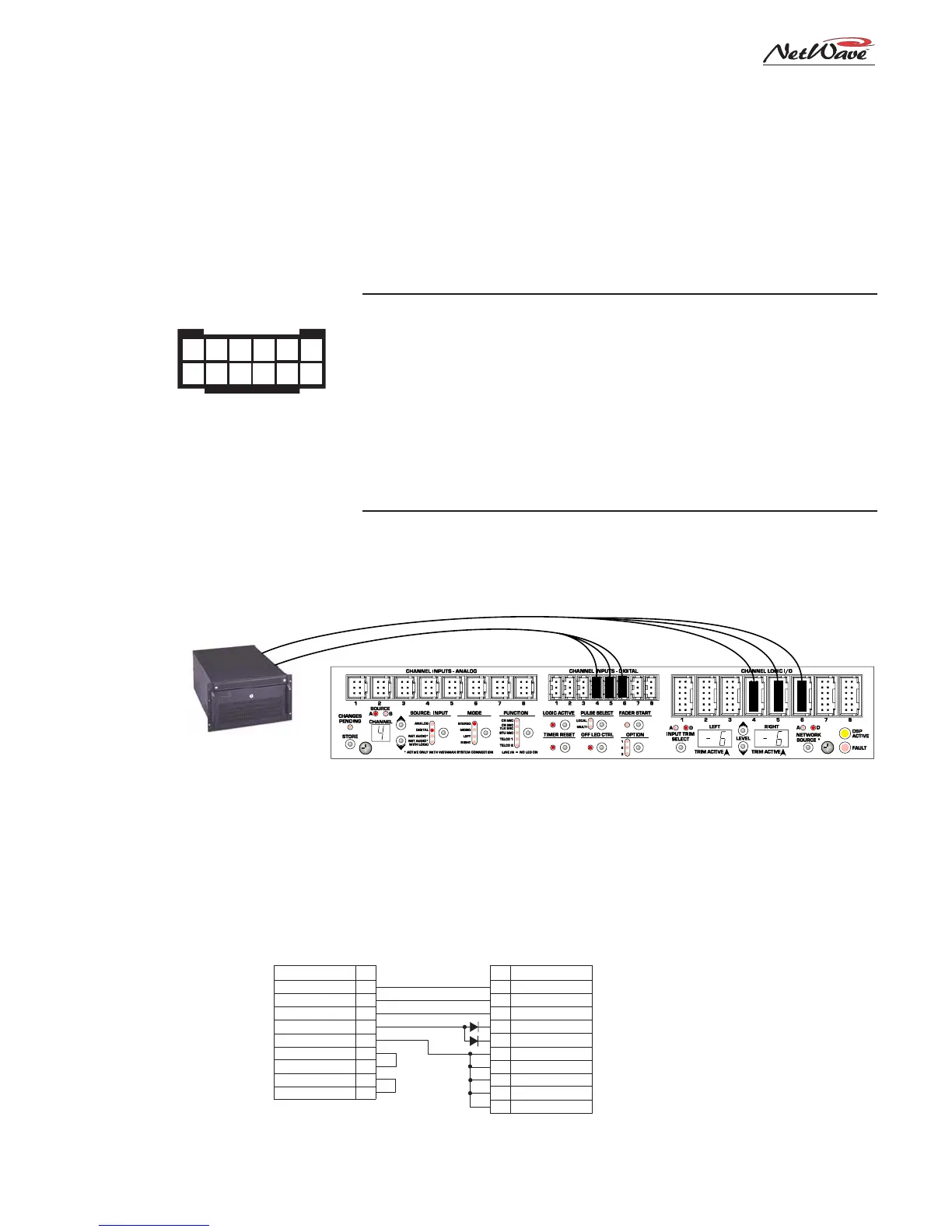
DSP & I/O Card
To Logic I/O 4, 5, 6
To Digital Inputs 4, 5, 6
Computer Playback System,
three channels connected to
channels 4, 5, 6, all source A
Channels 4, 5 and 6 Parameter Settings (A sources)
EXAMPLE OF A COMPUTER PLAYBACK SYSTEM CONNECTED TO CHANNELS 4, 5 AND 6
1. Input: set to Digital
2. Mode: set to Stereo
3. Function: LINE (no LEDs lit)
4. Logic Active: On
5. Timer Reset: On
6. Remote Off LED Ctrl: On
(for Ready control of Off LED)
7. Input Trim: -6 dB on both channels
8. Network Source: set to Digital
(sets these inputs as VistaMax sources)
TYPICAL COMPUTER PLAYBACK SYSTEM LOGIC WIRING
USING A GENERAL PURPOSE I/O CARD