12/20/11 888-2595-001 3-7
WARNING: Disconnect primary power prior to servicing.
Section 3 Operation
ZX Series
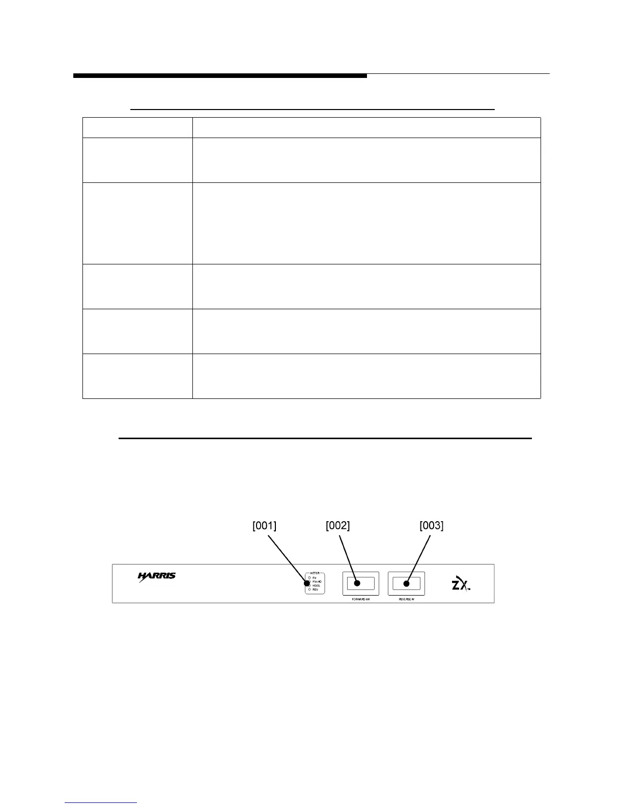
3.3 System Metering Assembly
Transmitter models with an output power of 7.5kW and above have a system metering
panel that displays the total system forward and reverse output power.
Figure 3-4 System Metering Panel
AC 1 FAULT
AC 2 FAULT
AC 3 FAULT
AC mains low fault LEDs
Indicates one or more AC mains inputs are below the 190V threshold
needed for the RF amplifying section to operate.
IPA 1 ON
IPA 2 ON
IPA on/off status LEDs
Indicates in one or both halves of the IPA module are switched on.
Both LEDs are behind the IPA module heatsink and may be seen
through the heatsink fins. Because the IPA module accepts the shared
voltage of all the PS modules, it is not possible to determine its on/off
status via the PS module DC OK LEDs.
PA CURRENT PA module current overload LED
Indicates that the PA module has shut down due to a current draw of
more than 22A.
PA TEMPERATURE PA module temperature overload LED
Indicates that the PA module has shut down due to a transistor flange
temperature greater than 99C.
PA REVERSE PWR PA module reverse power overload LED
Indicates that the PA module has shut down due to a reverse power at
its output of more than 25W approx.
Table 3-3 LEDs inside amplifier chassis
Item Description
 Loading...