Page 10
BCS6000C-9
BIAS POINT ADJUSTMENT
Bias adjusting screens are accessed via the MAIN MENU. Before firing the burner, verify the
OIL FIRING BIAS POINTS and GAS FIRING BIAS POINTS are set to the default values listed
below.
Point Oil/LP Gas
Light off 3.0 3.0
Low Fire 0.0 0.0
10% 5.0 10.0
20% 10.0 20.0
30% 15.0 30.0
40% 25.0 40.0
50% 35.0 50.0
60% 45.0 60.0
70% 55.0 70.0
80% 65.0 80.0
90% 77.5 90.0
100% 100 100
Setup an analyzer to monitor stack or drum emissions. With the burner firing in manual at
approximately 10% output, select the bias point setting screen. Allow the analyzer readings to
stabilize, then increase or decrease the fuel input, if required. Make small adjustments and
allow readings to settle after each change. Increase the burner firing rate to approximately 20%
and repeat the above adjustment procedure. Continue for the 30, 40, 50, etc. or extrapolate
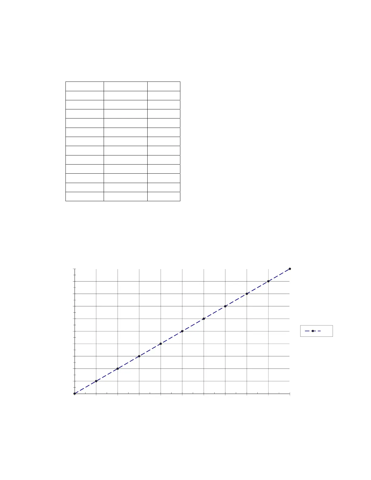
settings by plotting them on the chart shown in Figure 2. Record the resulting settings in the
Table provided in Appendix B. Press the MAIN button to exit and return to normal display.
Figure 2. Blank Chart for Plotting EVC Fuel Bias Settings
0
10
20
30
40
50
60
70
80
90
100
0 102030405060708090100
Motor Position, %
Heat Demand, %
Air
 Loading...