Page 13
BCS6000C-9
G. TROUBLESHOOTING
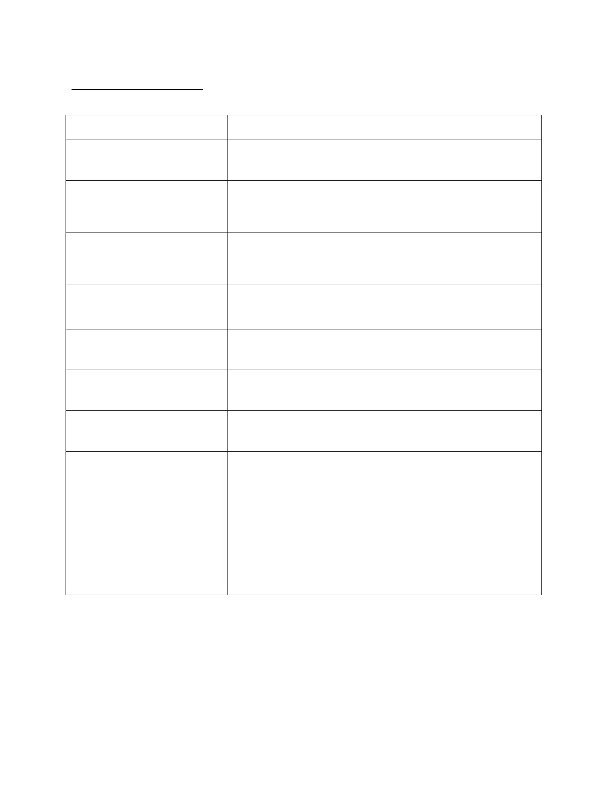
Use the HELP screens on the touch screen or refer to the following table.
MESSAGE DIAGNOSTICS
CONTROL MOTOR CALIBRATION
REQUIRED
The difference between the Zero and Span feedback values of each
motor must be greater than 3300. Verify that the motors travel full
stroke during the motor calibration procedure.
FUEL CONTROL MOTOR FAULT
* Indicates that the fuel control motor has failed to respond to the
motor positioning output signals of the PLC. Check fuse 5 on the
printed circuit board. Also monitor slot 4 outputs 4 and 5 and relays
R6 and R7.
AIR CONTROL MOTOR FAULT
* Indicates that the fuel control motor has failed to respond to the
motor positioning output signals of the PLC. Check fuse 45 on the
printed circuit board. Monitor slot 4 outputs 6 and 7 and relays R8
and R9.
CHECK PURGE AIR LIMITS & MAIN
FUEL VALVE PROOF OF CLOSURE
SWITCHES
Monitor slot 2 input 7, terminals 24 thru 24E. This message appears
if the purge air pressure limit, exhaust damper open limit, or any of
the fuel valve proof of closure switches fails to close.
CHECK LOW FIRE LIMITS
Monitor slot 2 input 5. Verify that all low fire limit switches are closed
(120Vac on terminal 21) when the control motors are in the low fire
start position.
HIGH STACK TEMPERATURE:
LOW FIRE HOLD
Check the low fire alarm setting on the RUN MENU screen. The
burner will be held at low fire until stack temperature falls below the
alarm setpoint
HIGH MATL. TEMPERATURE: LOW
FIRE HOLD
Check the low fire alarm setting on the RUN MENU screen. The
burner will be held at low fire until material temperature falls below
the alarm setting.
FLAME RELAY RESET REQUIRED
Monitor slot 1 input 6 and the ALARM indicator of the Honeywell
flame relay. This fault normally indicates that the pilot has failed to
ignite within the trial for ignition period. Verify that air, fuel and spark
are being supplied to the pilot. Other possibilities include:
1. Premature flame signal. If the flame meter indicates presence of
a flame before the ignition sequence is started, the flame relay will
lockout and the RESET indicator will come on. Check for fire in the
dryer drum or for a failed UV scanner.
2. Bad or missing ground. The Honeywell flame relay requires a
120Vac grounded neutral power supply for proper operation.
3. Flame amplifier failure. The flame amplifier may need to be
replaced.
* The control motor faults all indicate possible problems with the burner control motors or the
position feedback circuits. Silence the alarm horn and make note of the motor position
values displayed on the MOTOR CALIBRATION screen, then press the ALARM SILENCE
button a second time to reset the fault. Shut off the burner and verify that all control motors
drive to their ZERO and SPAN positions, and that the feedback signals change smoothly
as the
motors drive. If not, check fuse 99 and verify that 5Vdc exists between terminals 82 (+) and 81
(-). Also, check fuses 5 and 45 on the printed circuit board.
 Loading...