Page 14
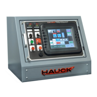
BCS6000C-9
MESSAGE DIAGNOSTICS
EXHAUST FAN FAULT
Monitor slot 2 input 0. Check the exhaust fan flow switch (power on
terminal 12) and the exhaust fan motor starter interlock (power on
terminal 13).
SECONDARY AIR INTERLOCK
FAULT
Monitor slot 3 input 1. Verify that the burner blower is running and
check the secondary air starter interlock (power on terminal 14).
LOW AIR PRESSURE
Monitor slot 2 input 1. Verify that the secondary air pressure switch
is made (power on terminal 16). For EcoStar I only, verify the
primary air interlock (terminal 15) and the primary air pressure switch
(terminal 15A) are also powered. For StarJet, MegaStar, and
EcoStar II burners, jumper terminals 14 to 15A in the burner J-Box.
LOW GAS PRESSURE
Monitor slot 3 input 4. Verify that the manual gas shutoff valve is
open and that the low gas pressure switch is made (power on
terminal 16A).
HIGH GAS PRESSURE
Monitor slot 3 input 0 and the high gas pressure switch (power on
terminal 17).
LOW OIL or LP PRESSURE
Monitor slot 3 input 5. Verify that the manual shutoff valve is open
and that the low pressure switch is made (power on terminal 17A).
HIGH OIL or LP PRESSURE
Monitor slot 3 input 2 and the high oil or LP pressure switch (power
on terminal 17B).
ATOMIZING AIR FAULT
Monitor slot 3 input 3. For StarJet, MegaStar, and EcoStar II
systems verify that the primary air interlock and pressure switch or
compressed air pressure switches are made (power on terminals
17C and 17D
OIL TEMPERATURE FAULT
Monitor slot 2 input 2. For heavy oil systems, verify that the oil
heater is operating and the oil temperature switches are made
(power on terminal 18).
HIGH STACK TEMPERATURE
Monitor slot 2 input 3. Check for power on terminals 25 and 26.
Observe the display and OUT indicator of the stack temperature
instrument. A full scale reading (842°F or 450°C) indicates an open
TC or broken wire
FLAME FAILURE
Indicates that the flame relay has locked out due to a flame failure.
Check burner setup.
MAIN FUEL VALVE FAULT
Monitor slot 2 input 6. This input must be received within 20
seconds after the pilot flame has been recognized. Verify that
jumper wires are installed on the control panel terminal strip
between terminals 22 and 29 for gas and between terminals 30 and
44 for oil. For some applications it may be necessary to remove
these jumpers and connect the valve open limit switch in the main
fuel valve instead. Consult Hauck’s Service Department for details.
REPLACE SCREEN BATTERY
Indicates low touchscreen battery voltage. Replacement batteries
are available from EZ Automation (Part No. EZ-BAT). Consult the
EZTouch Hardware User Manual for battery replacement
instructions.
REPLACE PLC BATTERY
Indicates low PLC battery voltage. The battery compartment is
located in the CPU. A replacement battery is available from Hauck
(Part No. 62311) or Automation Direct (Part No. D2-BAT-1).
 Loading...