Page 9
BCS6000C-9
E. ELECTRONIC VALVE CHARACTERIZATION
To facilitate burner setup and optimize emissions, the BCS6000 system has been equipped with
Electronic Valve Characterization (EVC). This feature provides for creation of separate motor
response curves for the air and fuel control motors. Regardless of fuel selection, the air control
motor, or VFD, directly follows the heat demand output of the temperature controller. For
example, 15% output from the temperature controller will result in the air control motor driving
15% open. Meanwhile, the fuel control motor will follow a separate curve established by setting
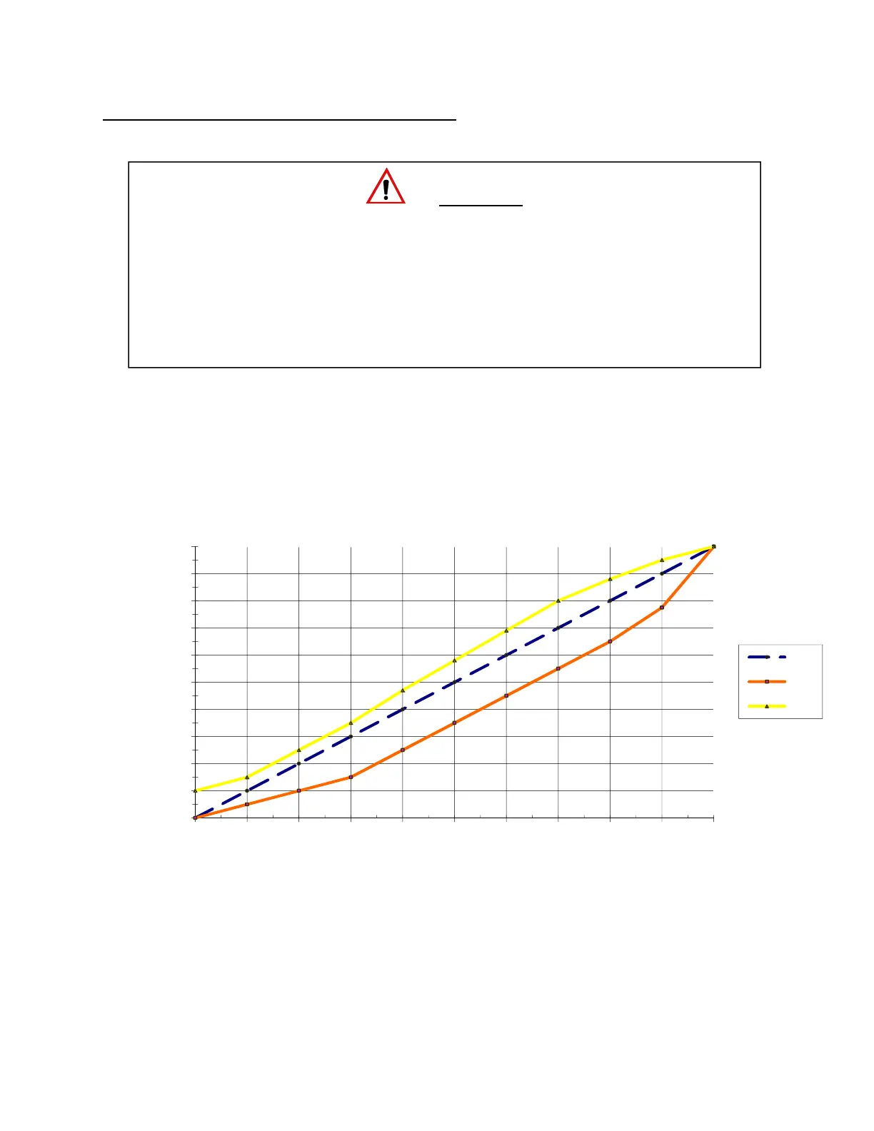
characterization (bias) points as shown in Figure 1.
Figure 1. Example of EVC Fuel Bias Settings
0
10
20
30
40
50
60
70
80
90
100
0 102030405060708090100
Motor Position,%
Heat Demand, %
Air
Oil
Gas
WARNING
Adjustment of this equipment by unqualified personnel can result in fire,
explosion, severe personal injury, or even death. This procedure requires the use of
a stack analyzer to properly adjust air/fuel ratio and optimize burner performance. It is
intended for qualified personnel, familiar with combustion systems and the interpretation
of stack emission readings. Electronic Valve Characterization is designed to provide for
minor adjustments to the air control valve position only. The low fire start positions and
overall valve strokes must be set by adjustment of the valve/motor linkages.