Page 36
BCS6000C-9
value, then press the RESET key on the STACK instrument to reset the fault and extinguish
the OUT indicator.
FLAME FAILURE TEST
Start the burner and establish the low fire burner flame.
Simulate flame failure by closing the manual shutoff valve downstream of the safety shutoff
valves, or as an alternative to closing the manual valve system, temporarily disconnect field
wire 87 from the control panel terminal strip.
After approximately three seconds the Honeywell flame relay will lockout and its red ALARM
indicator will be illuminated. The burner will shut off, the alarm will sound, and a ‘FLAME
FAILURE’ message will be displayed.
Silence the alarm and replace wire 87, or open the manual shutoff valve to resume normal
operation.
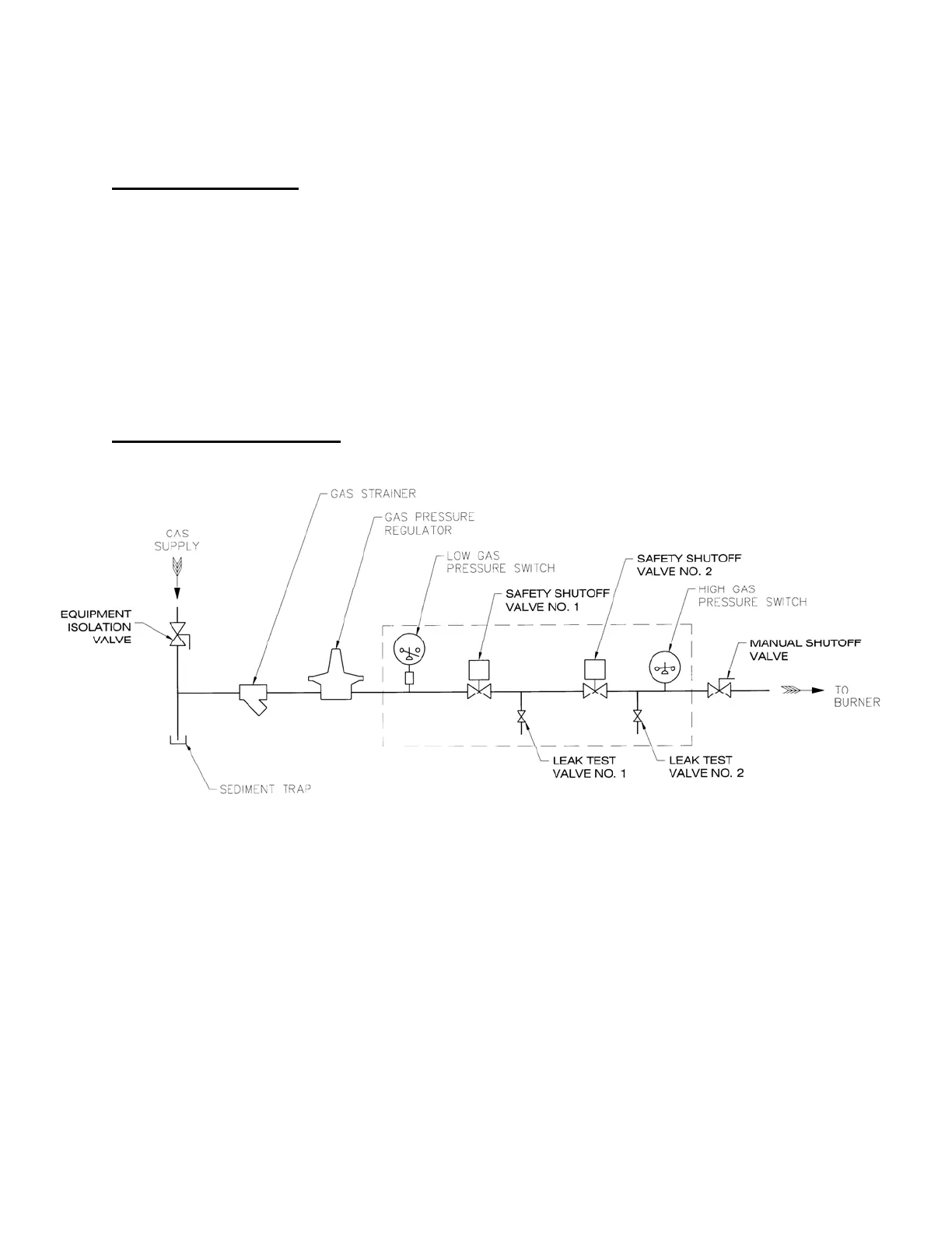
GAS VALVE LEAK TESTING
Refer to gas piping diagram for leak testing shown in Figure 1.
Figure 1. Gas Piping Diagram for Leak Testing
Close the manual shutoff valve downstream of Safety Shutoff Valve No. 2.
Open the equipment isolation valve upstream of Safety Shutoff Valve No. 1.
Bleed off trapped gas by opening both Leak Test Valves No. 1 and No. 2.
Close Leak Test Valve No 2.
Connect 3/16" (4.8mm) ID tubing to Leak Test Valve No. 1 and immerse the open end of
the tubing in a container of water. Hold the tubing vertically 1/8 to 1/4" (3 to 6 mm) below
the surface. If bubbles appear, record the leakage rate in bubbles/min and refer to the
IMPORTANT note at the end of this section.
Close Leak Test Valve No. 1 and apply auxiliary power to open Safety Shutoff Valve No. 1.
Wait several minutes so that any leakage through Safety Shutoff Valve No. 2 will have time
W7610
(NOT TO SCALE)
 Loading...