1-4 InstallatIon
P/N 0387183_V
U.S. & Canada 1-800-922-1919 • Mexico 1-800-890-2900 • WWW.HUSSMANN.COM
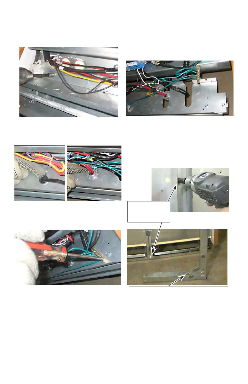
4. Remove the screws that attach the wireway pan to
the bottom assembly.
5. Detach the rubber and plastic gromets from the
wireway pan.
6. Remove the screws that attach the grounding lug to
the wireway pan.
7. Slide the wireway pan out, and remove it from the
case. Bumper brackets and supports are attached to
wireway pan. Removing the pan will remove the entire
assembly.
8. Remove the back, external braces from the rear of
the case as shown below. Braces will slide straight
back away from the case when nuts and screws are
removed.
6 nuts and 1
bottom screw per
external brace
Bottom screw is located approximately
10 inches inboard from the rear of the
case. Bottom screw location on removed
rear brace.