Do you have a question about the hawa Concepta 40 and is the answer not in the manual?
Specifies the intended application and scope of the hardware system for wooden doors.
Details maximum door weight, width, height, and thickness for both models.
Explains how product articles are identified by a 5-digit number.
Guides on integrated documents, metric measurements, and instruction retention.
Advises on safety precautions when concealing electrical appliances.
Provides guidance on environmentally friendly recycling of materials.
Explains the meaning of hazard symbols used in the assembly instructions.
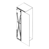
Visual overview of the left-hand installation system components.
Provides an overview of the optional Connector 55.
Provides an overview of the optional Connector 110 with/without base.
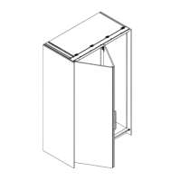
Visual overview of a two-door inset pivot sliding door system.
Displays all components identified by their respective position numbers.
Details planning requirements for inset doors.
Planning guide for two pivot sliding doors.
Planning for doors closing against base/top with Connector 55.
Planning for doors closing against base/top with Connector 110.
Planning details for doors installed in a wall recess.
Table for calculating door weight to size/height ratio for HAWA Concepta 40.
Provides dimensions for planning the cabinet layout and door integration.
Calculation guide for determining the required hardware depth.
Details precise drill hole positions for hardware installation.
Instructions for processing the left-side profiles.
Instructions for processing the right-side profiles.
Steps for pre-assembling the doors.
Pre-assembly steps for the cabinet side.
Pre-assembly steps for an outside pocket wall.
Steps for pre-assembling the dampener.
Pre-assembly steps for the upright component.
Instructions for aligning the cabinet during pre-assembly.
Assembly steps for the scissor and upright on the left side.
Assembly steps for the scissor and upright on the right side.
Steps for assembling the doors to the system.
Assembly of the door closing system.
Fine adjustment for door upright angle (19-30 mm).
Fine adjustment for door upright angle (31-50 mm).
Positioning the stop dampener for optimal performance.
Steps for adjusting the door height.
Fine adjustment for door clearance and alignment.
Fine adjustment for the front depth of the door.
General fine adjustment procedures for the doors.
Fine adjustment for the pull-in speed of the closing mechanism.
Steps for disassembling the door closing system from a fixed panel.
| Brand | hawa |
|---|---|
| Model | Concepta 40 |
| Category | Indoor Furnishing |
| Language | English |