9.Repeat7and8ontheoppositesideofthecutter
deck.
10.Checkthefront-to-rearbladeslope;referto
AdjustingtheFront-to-RearBladeSlope.
AdjustingtheFront-to-Rear
BladeSlope
Checkthefront-to-rearbladeslopewheneveryouinstall
thecutterdeck.Beforeyouchecktheslope,settheair
pressureinthetyrestotherecommendedlevel;referto
CheckingtheTyrePressure.Ifthefrontofthecutter
deckisnotwithinarangeof1/8to3/8inch(3to10
mm)lowerthantherearofthecutterdeck,adjustthe
bladeslopeasfollows:
1.Parkthetractoronalevelsurface.
2.Disengagethebladecontrol(PTO)andsetthe
parkingbrake.
3.Stoptheengine,removethekey,andwaitforall
movingpartstostopbeforeleavingtheoperating
position.
4.Checkandadjusttheside-to-sidebladelevelifyou
havenotcheckedthesetting;refertoLevelingthe
CutterDeckfromSide-to-Side.
5.Movetheheight-of-cutleverintothe“C”notch.
6.Measurethelengthoftherodextendingoutof
thefrontoftheadjustingblockonthesidesofthe
chassis(Figure61).Iftherodlengthisnot5/8inch
(16mm),removethehairpincotterandwasherfrom
theendoftherod(Figure61)andturntheroduntil
itextendsout5/8inch(16mm).
Figure61
1.Adjustingblock3.Hairpincotterandwasher
2.Longrod
4.CutterDeckmount
7.Installtheendoftherodintotheholeinthecutter
deckmountandsecureitwiththewasherand
hairpincotter.
8.Repeat6and7ontheoppositesideofthecutter
deck.
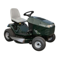
9.Checkthefront-to-rearslopebymeasuringbetween
thebottomofthecutterdeck(frontcenterandrear
center)andtheatsurface(Figure62).Ifthefrontis
notwithinarangeof1/8to3/8inch(3to10mm)
lowerthantherear,anadjustit.
Figure62
1.Measurefrontcenter
2.Measurerearcenter
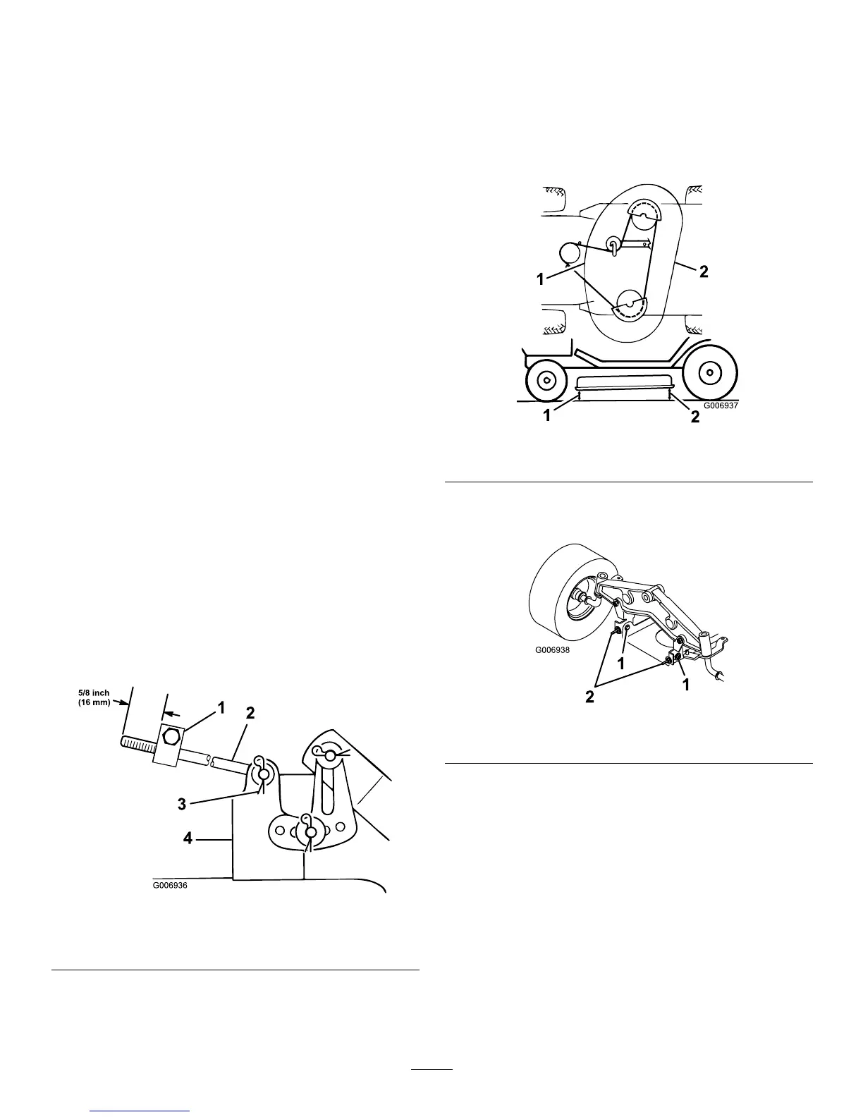
10.Slightlyloosenthefrontpivotplatemountingbolts
(Figure63).
Figure63
1.Pivotmountingbolt2.Eyeboltlocknut
11.Rotatethelocknutsontheeyeboltstochangethe
adjustment(Figure63).
Note:Toraisethefrontofthecutterdeck,tighten
theeyeboltlocknuts;tolowerthefrontofthecutter
deck,loosentheeyeboltlocknuts.
12.Afteradjustingbothoftheeyeboltlocknutsevenly,
checkthefront-to-rearslopeagain.Continue
adjustingtheeyeboltsuntilthefrontbladetipis0to
3/8inch(0to9mm)lowerthantherearbladetip
(Figure63).
40