23
Clip
HBMA0114-6.3 en
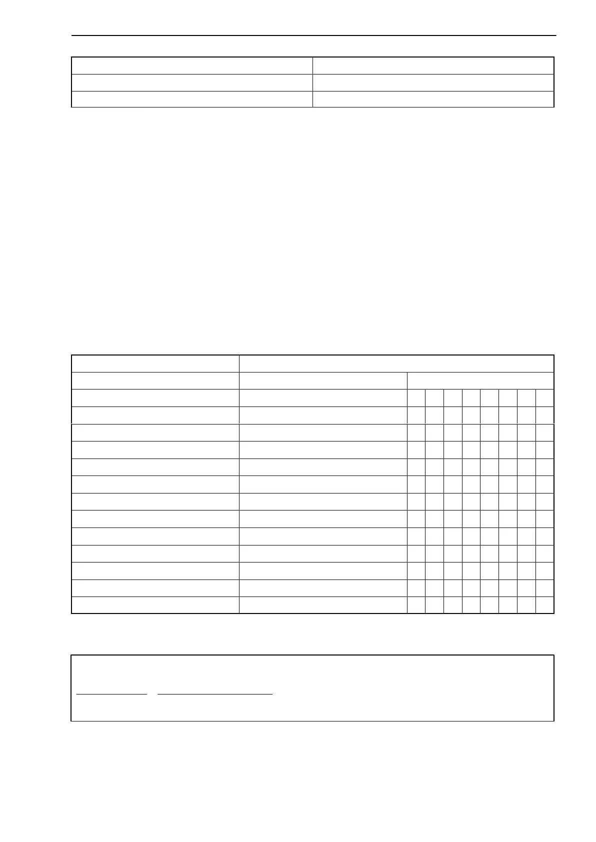
Bridge excitation voltage V
E
Transducer inductance L
B
2.5 V 2.5 ... 20 mH
1 V 6 ... 19 mH
• Measuring frequency range
The measuring frequency range is 10 Hz.
• Zero point
- Bring transducer into initial position (e.g. mechanical center position).
- Use digital voltmeter to measure output voltage, and use rotary switch S23
to adjust minimum indication (if necessary, use S22 to switch polarity); fine
balancing with P21 to 0.000 V.
• Measuring range
To obtain the maximum measurement resolution, the max. amplifier output-
voltage ("10 V) should be used.
AE501
V
E
= 1 V V
E
= 2.5 V switch position S21
mV/V mV/V 1 2 3 4 5 6 7 8
17.0-24.0 6.8-9.6 X X
22.0-32.0 8.8-12.8 X X
30.0-42.0 12.0-16.8 X X
39.0-55.0 15.6-22.0 X X
52.0-73.0 20.8-29.2 X X
68.0-97.0 27.2-38.8 X X
90.0-128.0 36.0-51.2 X X
118.0-169.0 47.2-67.6 X X
156.0-223.0 62.4-89.2 X X
207.0-292.5 82.8-117.0 X X
272.0-387.5 109.0-155.0 X X
360.0-512.5 144.0-205.0 X X
Tab. 4.3: Nominal displacement depending on the bridge excitation voltage V
E
Part load
Nominal load
•
10 V
Measuring range in V
• Sensitivity in mVńV +
Nominal measurement
value (Range) in mVńV
Formula: