34
Clip
HBM A0114-6.3 en
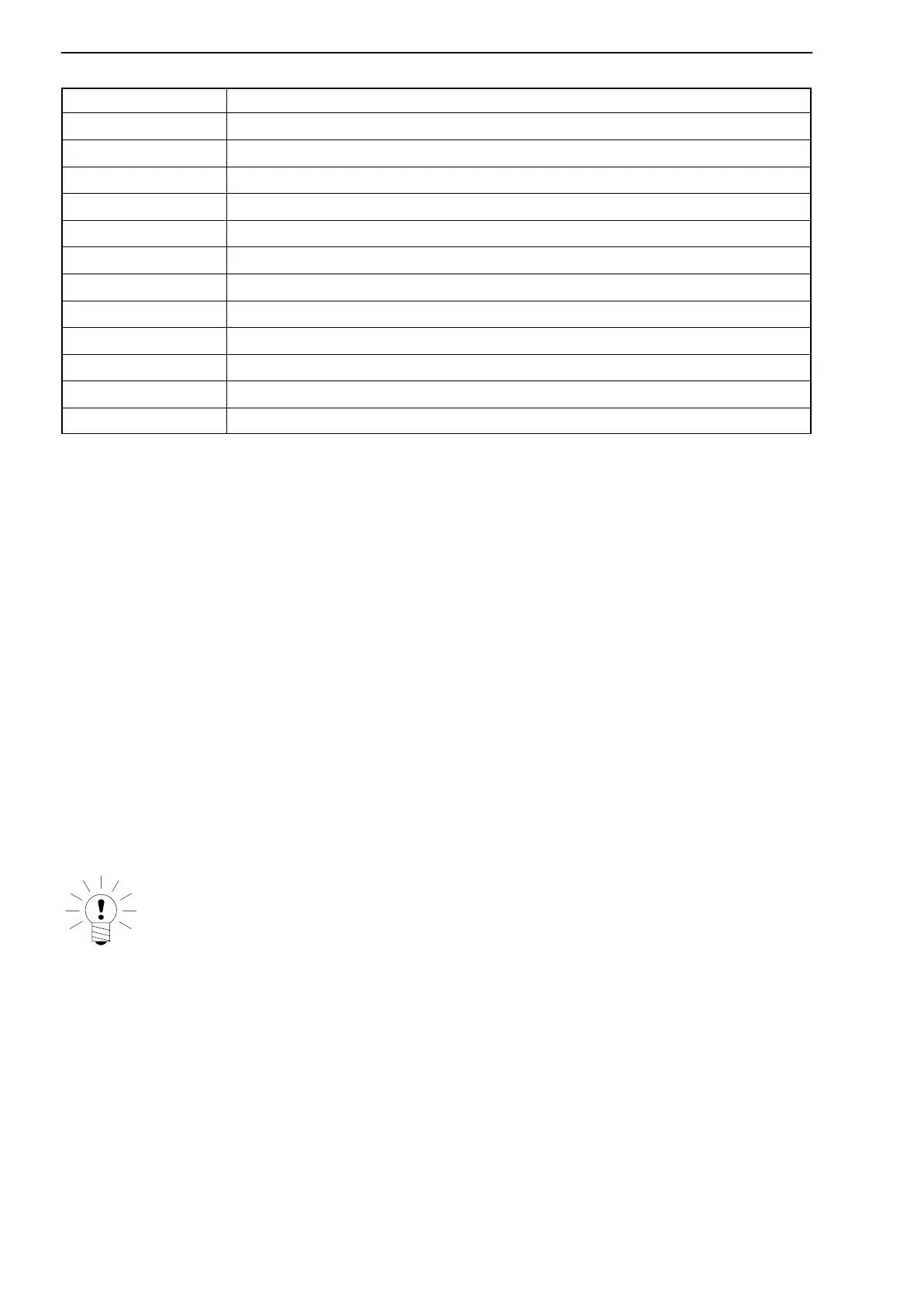
Terminal
Function
1 Operating-voltage zero
2 Input voltage "10 V
3 Operating-voltage zero
4 Peak-value store output-voltage "10 V
5 Tare unit output-voltage "10 V
6 Control output: valid tare (24 V DC)
7 Ground (external for control inputs)
8 Run/Hold peak-value store (24 V DC) control input
9 Peak/Clear peak-value store (24 V DC control input)
10 Tare (24 V DC control input)
11 Supply voltage 0 V
12 Supply voltage 15 ... 30 V DC (unregulated)
Tab. 5.1: Terminal assignment
5.3.1 Voltage supply
The automatic tare and store unit must be supplied with an external supply
voltage of 15 V to 30 V. Terminals 11 and 12 are used for connection.
5.3.2 Inputs / Outputs
Inputs
Connect to terminals 1 and 2 the output signal supplied by the amplifier con-
nected in series.
Outputs
The TS101 output signals can be picked up at terminal 4 (peak value) and ter-
minal 5 (net value). They can be used as the input signal for an indicator (load
resistance >5 kΩ) as shown in Fig. 5.7.
NOTE
Screened cable should be used for the analog input and output signals
to ensure proper functioning even if the components are exposed to
high EMC-levels.
5.3.3 Control inputs / Control output
The control inputs (terminals 7 ... 1 0) are electrically isolated from the proces-
sor. They must be connected to an external ground (e.g. PLC) and 24 V (as
control signal).