9
U2A
HBMA1261−2.2 en/de/fr
4 Connection
4.1 Notes on cable routing
Electrical and magnetic fields often cause the introduction of disturbing
voltages into the measuring circuit.
Please note the following hints:
• Use only screened, low capacitance measuring cable (cable from HBM
fullfills these requirements).
• Do not lay the measuring cable parallel to power and control lines. If this is
not possible (e.g. in cable ducts), the measuring cable can be protected,
e.g. by steel conduit.
• The stray fields of transformers, motors and contactors must be avoided.
4.2 Connection technique
Strain-gage based load cells can be connected to:
• carrier frequency
• DC-measuring amplifiers.
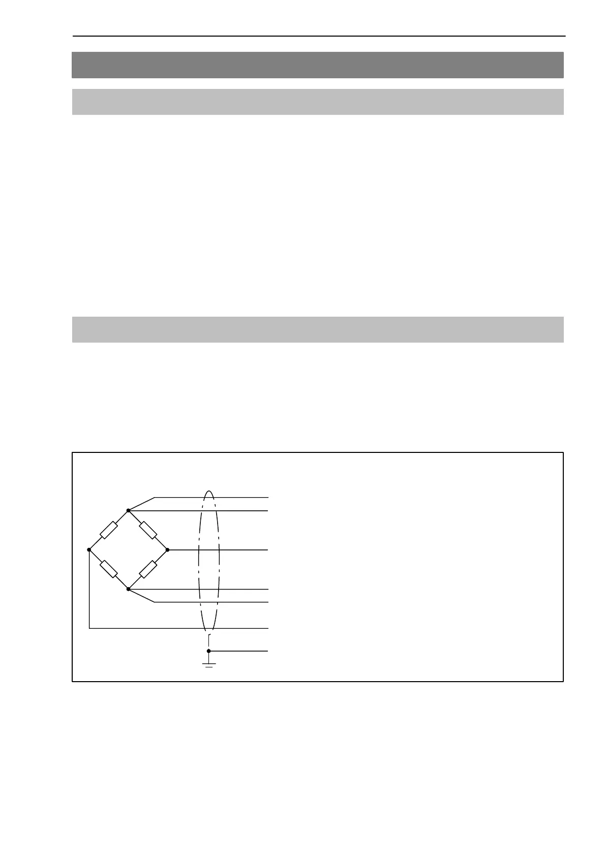
The transducer connection is implemented using the six-wire technique. The
connection assignment can be taken from the following illustration.
wh (white)
bk (black)
gy (grey)
Shield / filler connected with housing
gr (green)
rd (red)
−
Excitation (−)
Sense
Signal (+)
bu (blue)
Sense
Signal (−)
Excitation (+)
Wiring code (6-wire−technique)
Fig. 4.1: Transducer with six-core cable