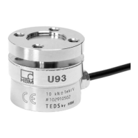
U93
14
A2081-2.2 en/de/frHBM
45° or 22.5°
offset in the drawing
M
A
M
A
customer
side
customer
side
Base
Flange
ØC
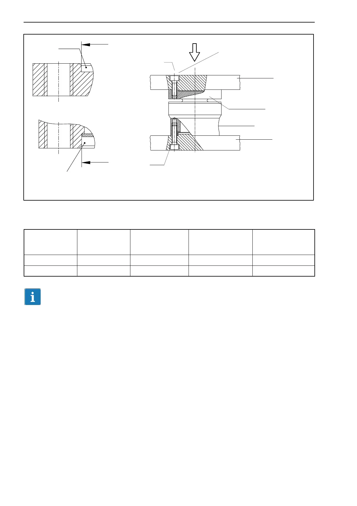
Center the U93 over diameter C!
admissible
centering depth
1 mm
admissible
centering depth 1.5 mm
ØC
F
Fig. 5.2: Force transducer installation
Nominal
(rated) force
(kN)
Centering
diameter C
H8
Tightening
torque M
A
(NVm)
Screws for
transducer
mounting
min. floor side
thread reach
(mm)
1kN … 10kN 18 9 4 x M5; 12.9 5
20kN … 50kN 32 16 8 x M6; 12.9 8
Important
When screwing through the upper tapped hole, make sure that a gap remains
between the screw and the transducer body, even when the nominal (rated)
force is applied. Otherwise there would be a force shunt, that could lead to
measurement errors.


 To Next Page