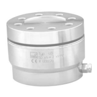
The AED9301B is a digital transducer electronics unit, part of the AED component family, designed to digitally condition signals from mechanical measurement sensors and integrate them into a bus network. It serves as a basic device for PROFIBUS communication, offering a streamlined solution for connecting complete measurement chains to a field bus with minimal effort.
Function Description:
The primary function of the AED9301B is to directly digitize and condition measurement signals at the transducer location. It allows for the connection of Strain Gage (SG) transducers in a full-bridge circuit directly to a PROFIBUS DP network. This integration simplifies the process of bringing measurement data into automation systems like SIEMENS SIMATIC S7 or PCs.
The basic device provides mechanical protection (IP65) for the amplifier board and ensures EMC protection. It includes a slot for an AD103C amplifier board (which is not part of the basic device's scope of supply). The AED9301B also manages the power supply for the amplifier motherboard and transducer excitation, with full electrical isolation of all connections.
Key functionalities include:
- Signal Conditioning: Digitizes and conditions signals from mechanical measurement sensors.
- PROFIBUS DP Interface: Electrically isolated from the amplifier and digital inputs/outputs, supporting RS485 transmission with a maximum baud rate of 12 Mbit/s. Node addresses are set via BCD-coded rotary switches (S5 and S4). Bus termination can be activated at both ends of the PROFIBUS line using switch S2, and the module can be disconnected for diagnostic purposes via switch S3.
- Digital Inputs/Outputs (I/O): Two digital inputs (IN1, IN2) and four digital outputs (OUT1-OUT4) are provided. These are electrically isolated from the amplifier and PROFIBUS. The inputs enable functions such as triggering measured values (MAV), taring, and controlling filling/dosing processes. The outputs can be used to control processes via four limit values (LIV1-LIV4) or for specific dosing mode functions like "Coarse Flow," "Fine flow," "Ready signal / emptying," "Tolerance+ overrun," and "Alarm."
- Diagnostic Bus: An RS485 2-wire bus (TB/RB and TA/RA, GND) is available for analyzing dynamic processes. This bus operates at a fixed rate of 38400 bit/s, 8E1, and does not require external termination resistors. It allows for reading parameters (read-only), individual measured values (MSV?), trigger results, and dosing results.
- Power Supply: Provides power for the amplifier motherboard and transducer excitation (5 VDC).
The AED9301B is designed to work with the PC software AED PANEL 32 for parameter settings, dynamic measurement signal display, and comprehensive system analysis. It can also connect to the HBM display unit DWS2103, which supports all implemented AED functions.
Important Technical Specifications:
- Transducer Connection: Supports SG transducers in a full-bridge circuit.
- Total Transducer Bridge Resistance: 80 Ω to 4000 Ω. For resistances >1000 Ω, increased noise (measurement ripple) should be considered.
- Bridge Supply Voltage: 5 VDC, supplied by the AED9301B basic device.
- Wiring: Supports 6-wire circuitry to compensate for cable length effects on measured values. 4-wire circuitry is also possible but is more susceptible to temperature-dependent measurement errors with long cables.
- Supply Voltage (External): DC voltage +18 V to +30 V.
- Current Consumption: 200 mA + current of control outputs OUT1-4 (at 80 Ω bridge resistance and 24 V power). Specific consumption values vary with supply voltage (e.g., ≤250 mA at 18 V, ≤200 mA at 24 V, ≤170 mA at 30 V).
- Digital Output Current: Can drive ohmic and inductive loads with currents up to approximately 0.5 A per output.
- PROFIBUS Baud Rate: Up to 12 Mbit/s.
- PROFIBUS Cable Length: Varies with bit rate (e.g., 1200 m at 9.6 kbit/s, 100 m at 12000 kbit/s).
- PROFIBUS Node Address: Settable from 3 to 99 via S5 and S4 rotary switches. Factory default is 03.
- Diagnostic Bus Baud Rate: 38400 bit/s, 8E1 (fixed).
- Protection Class: IP65 (mechanical protection).
- Electrical Isolation: Full electrical isolation between amplifier, PROFIBUS, and digital I/O.
Usage Features:
- Easy Integration: Connects SG transducers directly to PROFIBUS DP, simplifying measurement chain setup.
- Flexible Wiring: Offers 6-wire connection for improved accuracy over long cables and 4-wire connection options.
- Configurable I/O: Digital inputs and outputs can be configured for various control and measurement tasks, including limit value control, triggered measurements, and dosing processes.
- Diagnostic Capabilities: A dedicated diagnostic bus allows for analysis of dynamic processes and reading of internal parameters and results, supported by HBM AED_Panel32 software and DWS2103 display unit.
- PROFIBUS Addressability: Node address is easily set via rotary switches.
- Bus Termination: Integrated slide switches for PROFIBUS bus termination (S2) and diagnostic bus link (S3).
- LED Indicators: Four LEDs (LED1-LED4) provide visual feedback on PROFIBUS status (power supply, data exchange, diagnostics, error).
Maintenance Features:
- No Internal Repairs: It is strictly forbidden to carry out repairs or soldering work on motherboards or replace components by unauthorized personnel. Repairs must only be performed by HBM-authorized individuals.
- Factory Defaults: All factory defaults are stored safely and can be reset at any time using the TDD0 command.
- Cable Shielding: Proper connection of cable shielding to PG glands is crucial for EMC protection and potential equalization.
- Electrostatic Discharge Prevention: Measures must be taken to prevent electrostatic discharge during installation and cable connection to avoid damaging the electronics.
- Cleanliness: The equipment should be kept clean and dry to ensure proper operation.
- Disposal: Old devices must be disposed of separately from normal household garbage, in accordance with national and local environmental protection regulations.