Connecting the supply voltage
13
AED9301B HBM
3.2 Connecting the supply voltage
The power supply must meet the following requirements:
AED9301B
DC voltage +18 V...+30 V
Current consumption 200 mA + current of control outputs OUT1...4
(at 80 bridge resistance and 24 V power)
Calculating total current consumption (at 80 bridge):
Current consumption for 18 V power supply: 250 mA + IOUT 1...4
Current consumption for 24 V power supply: 200 mA + IOUT 1...4
Current consumption for 30 V power supply: 170 mA + IOUT 1...4
I
OUT 1...4
= control outputs current
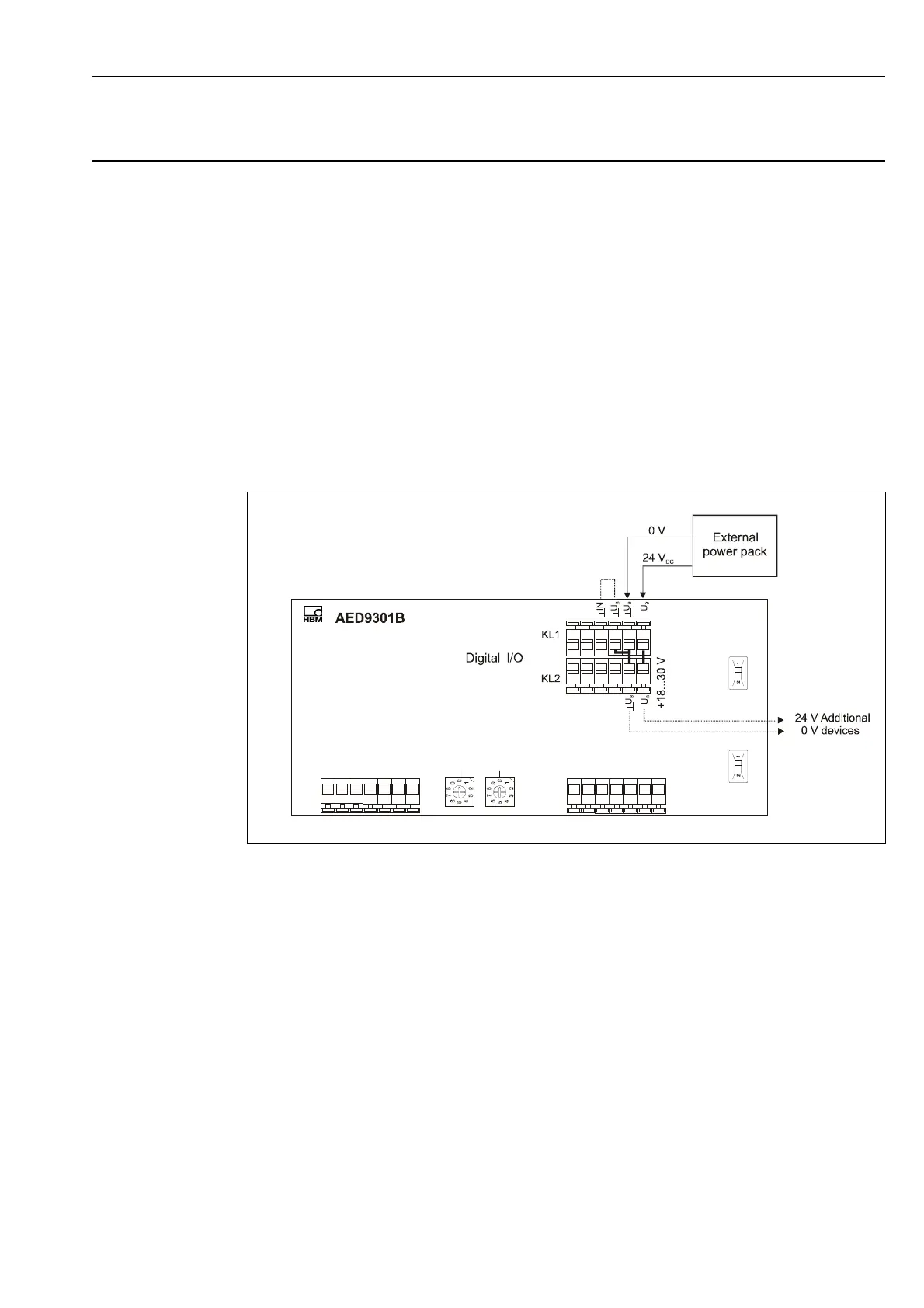
Fig. 3.2-1: Power supply connection
The AED supply voltage can be connected at terminals KL1 and KL2. The three ground ter-
minals and the two voltage terminals are each interconnected internally. The supply voltage
coming from the power pack is connected at terminal KL1; this supply voltage can be routed
to other devices at terminal KL2.
Electrically isolated digital outputs OUT1...OUT4 are also supplied from this voltage. The po-
tential separation occurs in the AED direction. Consequently the units controlled from
OUT1...4 can also be fed from U
B
(see Connection of digital inputs/outputs).
Control inputs IN1 and IN2 are initially electrically isolated from supply voltage U
B
. The two
grounds (ground U
B
and ground IN) can be connected to terminal KL1, if required (see Con-
nection of digital inputs/outputs).