8
Electrical connections
HBM AED9301B
3 Electrical connections
The AED9301B basic device comes with a connection diagram.
When making the connections, please ensure that the wires of the cable do not protrude
beyond the connection terminals (risk that loops may form). Please make sure that the
cable shielding is properly connected to the PG gland (see the AED9301B cable connec-
tion via PG glands section).
If it should be necessary, a separate cable can be used to establish potential equalization
between the transducer and the AED and between the AED and the Master control unit
(grounding concept). The cable shielding must not be used for this potential equalization.
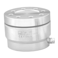
3.1 Transducer connection
The transducer connection must always be assigned (connect the transducer).
Fig. 3.1-1: Transducer connection in 6-wire circuitry (HBM color-coding)