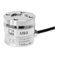
U93
16
A2081-2.2 en/de/frHBM
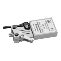
wh (white)
bk (black)
rd (red)
bu (blue)
gn (green)
gy (gray)
ye (yellow)
Measurement signal (+) U
A
Excitation voltage (+) U
B
Sense lead (-) and TEDS
Sense lead (+)
Excitation voltage (-) U
B
and TEDS
Measurement signal (-) U
A
Cable shield, connected to the housing
Fig. 6.1: U93 pin assignment (six‐wire configuration)
Tip
Swap the white and red cable wires over, if you need a negative output volt
age at the amplifier under compressive loading.
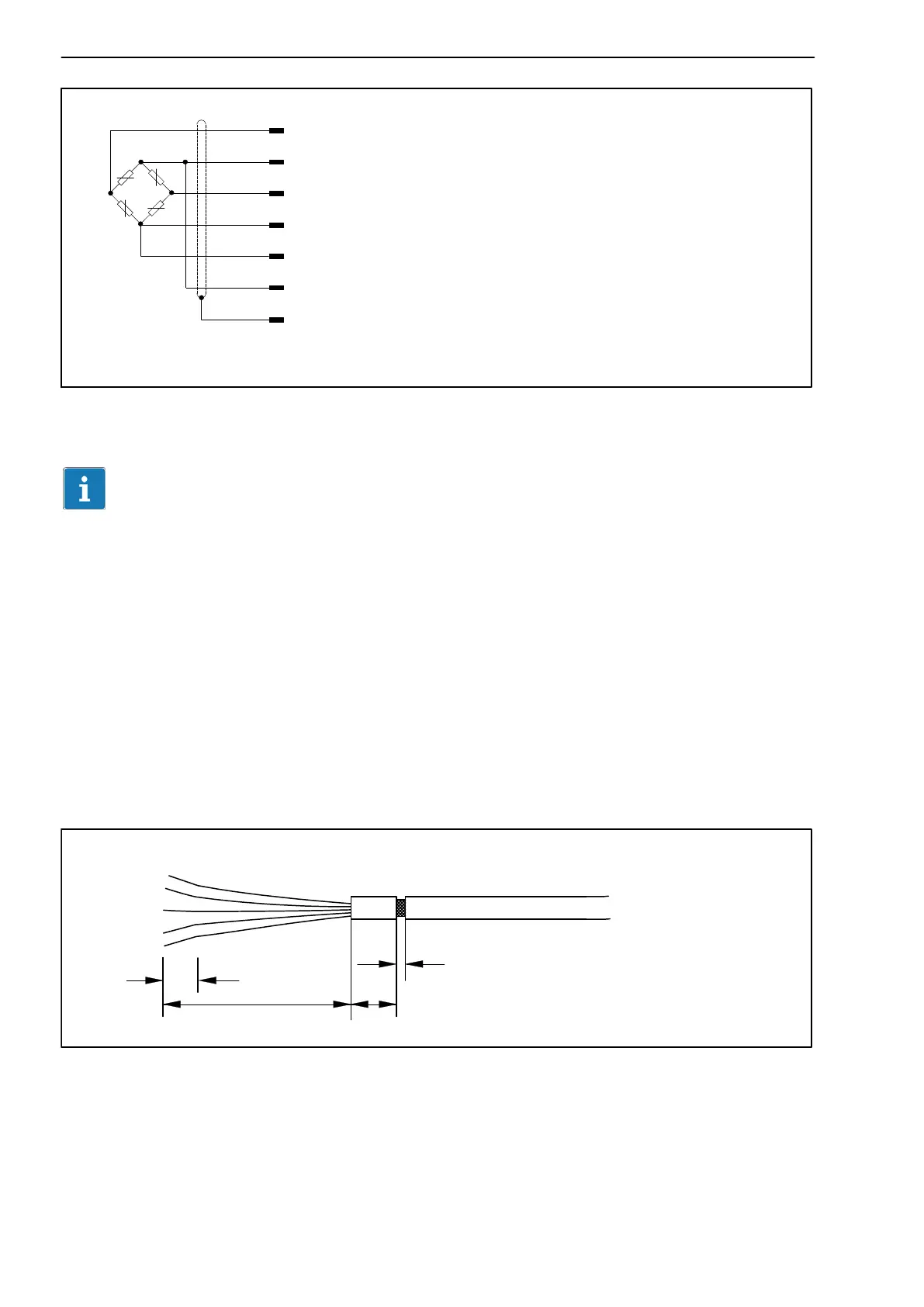
6.2.1 Connecting to terminals
1. Cut the cable sheath as shown in Fig. 6.2, to gain access to the shield.
2. Connect the shield extensively to the housing ground.
6.2.2 Connecting to a plug
Connect the cable shield extensively to the connector housing.
Cable sheath cut open around the
circumference and pushed forward by about
2 mm
100
10
10
2
Fig. 6.2: Cable sheath with incision
 Loading...