9
Heat Controller VFH InverterFlex
®
- Outdoor Ductless Mini-Split
Condensate Drainage
• For heat pump models only.
• Condensate and defrosted water created by the
unit operating in heat mode should be routed
and drained away from the unit.
• Parts needed for condensate drainage are not
factory supplied; they are commercially available.
• Fit the rubber washer onto the drain connector, then
insert the drain connector into the hole on the base
pan of the outdoor unit. Secure into place. (Fig. 11)
• Connect a locally purchased drain hose. Install
hose to the hose barb end of the drain connector.
• Route the hose to drain location away from
the unit.
• Repeat for each hole on the base of the unit, as
needed.
Fig. 11
Drain-water hole
Bottom frame
Drain plug
Drain connector
Hose (5/8” (16mm) I.D.
!
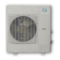
FIG. 10 42KBTU/H
42.8 in. (1087mm)
40 in. (1015mm)
24.84 in. (631mm)
7.52 in. (191mm)
43.43 in. (1103mm)
17.32 in. (440mm)
15.79 in. (401mm)
3.9 in.
(99mm)
17.72 in. (450mm)
14.25 in. (362mm)
3.0 in.
(76mm)
4.76 in.
(121mm)
39.13 in. (994mm)
FIG. 9 36KBTU/H
36.22 in. (920mm)
24.62 in. (610mm)
31.06 in. (789mm)
16.81 in. (427mm)
15.55 in. (395mm)
14.57 in. (370mm)
9.02 in. (153mm)
3.78 in. (96mm)
3.0 in.
(76mm)
6.97 in.
(177mm)
3.78 in.
(96mm)