EasyManua.ls Logo

Heat Controller HTV Series User Manual

Heat Controller HTV Series
51 pages
To Next Page IconTo Next Page
Page #1 background imageLoading...
Page #1 background image
Heat Controller, Inc. 1900 Wellworth Ave. Jackson, MI 49203 (517)787-2100 www.heatcontroller.com
INSTALLATION, OPERATION
& MAINTENANCE
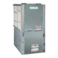
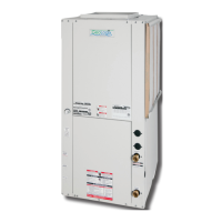
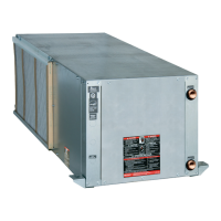
HTV/HTD/HTH Series
Two-Stage
Geothermal Heat Pumps
2 to 6 Tons

Other manuals for Heat Controller HTV Series

Questions and Answers:

Heat Controller HTV Series Specifications

General IconGeneral
CategoryHeat Pump
HSPF RatingUp to 10
StagesVariable Speed
RefrigerantR-410A
SeriesHTV
Heating CapacityUp to 60, 000 BTU/h
Cooling CapacityUp to 60, 000 BTU/h
Voltage208/230V

Summary

INSTALLATION, OPERATION & MAINTENANCE

SAFETY

Safety Warnings

Critical safety warnings and precautions for installation and operation.

General Information

PRE-INSTALLATION

Steps and checks required before installing the unit.

UNIT PHYSICAL DATA

Duct System Installation

VERTICAL UNIT LOCATION

Guidelines for selecting and preparing indoor locations for vertical units.

CONDENSATE PIPING

Horizontal Unit Location

Mounting Horizontal Units

Guidance on using factory-installed hanger kits for horizontal unit suspension.

Piping Installation

Ground-Loop Heat Pump Applications

Open Loop-Ground Water Systems

Hot Water Generator

Electrical - Line Voltage

Electrical - Power Wiring

Electrical - Power & Low Voltage Wiring

THERMOSTAT CONNECTIONS

Wiring instructions for connecting thermostats to the ECM interface board.

LOW WATER TEMPERATURE CUTOUT SELECTION

Field selection of low water temperature limits using jumpers.

Electrical - Low Voltage Wiring

Electrical - Thermostat Wiring

ECM Blower Control

Typical Wiring Diagram

CXM Controls

Safety Features - CXM Controls

Lockout

Control enters lockout mode after consecutive faults, storing the last fault.

High Pressure Switch

Protection against high refrigerant pressures, causing immediate compressor de-energization.

Unit Commissioning And Operating Conditions

Unit and System Checkout

Unit Start-Up Procedure

Step-by-Step Start-Up

Detailed sequence of checks and adjustments for unit start-up.

Two factors determine the operating limits

Unit Operating Pressures and Temperatures

Preventive Maintenance

Functional Troubleshooting

HP Fault - Code 2

Diagnosing high-pressure faults related to water or airflow.

LP/LOC Fault- Code 3

Troubleshooting low pressure and loss of charge faults.

FP1 Fault - Code 4

Diagnosing faults related to water coil low temperature limits.

FP2 - Code 5

Diagnosing faults related to air coil low temperature limits.

Condensate Fault - Code 6

Over/Under Voltage - Code 7

Unit Performance Sentinel - Code 8

Unit Short Cycles

Only Fan Runs

Only Compressor Runs

Unit Does Not Operate in Cooling

Performance Troubleshooting

Insufficient Capacity/Not Cooling or Heating Properly

Addressing issues with reduced cooling or heating capacity.

Low Refrigerant Charge

Diagnosing and correcting low refrigerant charge issues.

High Head Pressure

Low Suction Pressure

Low Discharge Air Temperature in Heating

High Humidity

Troubleshooting Form

Related product manuals