18
VFH InverterFlex
®
- Outdoor Ductless Mini-Split Heat Controller
Electrical Work
Outdoor unit power and
communication cable wiring
1. Remove the electrical control cover from the
outdoor unit (Fig. 13).
2. Connect power supply wires to the outdoor unit’s
terminal strip (Fig. 14-19).
3. Connect the communication cable from the
indoor unit to the outdoor unit’s terminal strip on
the left side. Repeat for each indoor unit (Fig.
14-19).
4. Connect the ground wire of the communication
cable to the ground terminal (Fig. 14-19).
5. To prevent water from entering in the unit, form a
loop in the cable (Fig. 13).
6. Insulate any unused conductors with electrical
tape, so that they do not touch any other
exposed electrical or metal parts.
7. Replace the electrical control cover that was
removed in Step 1.
Fig. 13
Cover
Screw
Loop the
cable
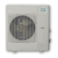
Air inlet (rear)
Air outlet
Air inlet (side)
1. The power cable should be placed in the hole
under connection cable cover.
2. If connecting two indoor units, the connection cable
should be placed in hole A and hole B.
3. If connecting three indoor units, the connection
cable should be placed in hole A, B and C.
4. If connecting four indoor unit, the connection cable
should be placed in hole A, B, C and D.
5. If connecting ve indoor units, the connecting
cables should be places in holes A, B, C, D and E.
Fig. 14