Heat Controller, Inc. HTV/HTD/HTH SERIES
18
GROUND-WATER HEAT PUMP APPLICATIONS
If water hammer persists, a mini-expansion
tank can be mounted on the piping to help
absorb the excess hammer shock. Insure
that the total ‘VA’ draw of the valve can be
supplied by the unit transformer. For
instance, a slow closing valve can draw up
to 35VA. This can overload smaller 40 or
50 VA transformers depending on the other
controls in the circuit. A typical pilot
operated solenoid valve draws
approximately 15VA. Note the special
wiring diagrams for slow closing valves
(Figures 12 and 13).
FLOW REGULATION
Flow regulation can be accomplished by two
methods. One method of flow regulation
involves simply adjusting the ball valve or
water control valve on the discharge line.
Measure the pressure drop through the unit
heat exchanger, and determine flow rate
from Table 8. Since the pressure is
constantly varying, two pressure gauges
may be needed.
Adjust the valve until the desired flow of 1.5
to 2 gpm per ton is achieved. A second
method of flow control requires a flow
control device mounted on the outlet of the
water control valve. The device is typically
a brass fitting with an orifice of rubber or
plastic material that is designed to allow a
specified flow rate. On occasion, flow
control devices may produce velocity noise
that can be reduced by applying some back
pressure from the ball valve located on the
discharge line. Slightly closing the valve
will spread the pressure drop over both
devices, lessening the velocity noise.
NOTE: When EWT is below 50°F, 2 gpm
per ton is required.
WATER COIL LOW TEMPERATURE LIMIT
SETTING
For all open loop systems the 30°F FP1
setting (factory setting-water) should be
used to avoid freeze damage to the unit.
See “Low Water Temperature Cutout
Selection” in this manual for details on the
low limit setting.
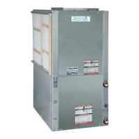
Figure 6b: Typical Open Loop / Well Application