Page 236
(
/
)
Depress the US6 bunon. The display should read
ug circuit board
D (#B5-1418) into the extender
~ ~
6603.6. board. First, remove the
set
of extenderboaFd~piiin
the left for which there are no sockets on board D.
I/)
De~ress
the
LSB button. The dis~lav should read
"
. .
6606.4.
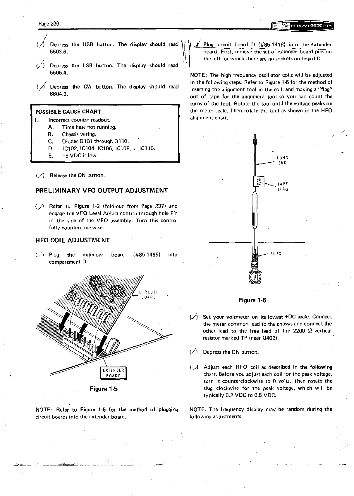
NOTE: The high frequency oscillator coils will be adjusted
in the following steps. Refer to Figure
1-6 for the method of
Depress
the
CW
The
display
should
read
inserting the alignment tool in the coil, and making
a
"flag"
6604.3.
out of tape for the alignment tool so you can count the
POSSIBLE CAUSE CHART
1. Incorrect counter readout.
A. Time base not running.
6. Chassis wiring.
C. Diodes
Dl07 through 0110.
D.
IC102. IC104, IC106. IC108, or IC110.
E.
+5
VDC
is
low.
J
turns of the tool. Rotate the tool until the voltage peaks on
the meter scale. Then rotate the tool as shown in the HFO
alignment chart.
(/I
Release the ON button.
PRELIMINARY
VFO
OUTPUT ADJUSTMENT
(,A
Refer to Figure 1-3 (fold-out from Page 237) and
engage the VFO Level Adjust control through hole FY
in the side of the VFO assembly. Turn this control
fully counterclockwise.
HFO COIL
ADJUSTMENT
II
(,,"I
Plug the extender board (#85-1465) into
SLUG
compartment D.
Figure
1-6
(A
Set your voltmeter on its lowest +DC scale. Connect
the meter common lead to the chassis and connect the
other lead to the free lead of the 2200
S2
vertical
resistor marked
TP
(near Q402).
(1)
Depress the ON button.
(J
Adjurt each HFO coil as described in the following
chart. Before you adjust each coil for the peak voltage,
turn
it
counterclockwise to 0 volts. Then rotate the
Figure
1-5
slug clockwise for the peak voltage, which will be
typically 0.2 VDC to 0.5 VDC.
NOTE: Refer to Figure
1-5
for
the method of plugging
NOTE: The frequency display may be random during the
circuit boards into the extender board.
follow~ng adjustments.