Page
287
X-RAY VIEW
(Shown
from
component
side)
VOLTAGECHART
(Shown
from
component side)
TRANSMITTER VOLTAGES
ItZO%I
NOTES:
1.
BANDSWITCH IN 3.5POSITION
2.
MODE SWITCH IN TUNE POSITION
3.
METER SWITCH IN
PWR
POSITION
NOTE:
Heath part numbersthat correspond to the circuit
4
MtC/CW-LEVEL FULLY COUNTERCLOCKWISE
component numbers will
be
found in the Parts List starting
on Page
31
of this Manual.
0
DC VOLTAGE
IN
RECEIVE OR TRANSMIT MODES
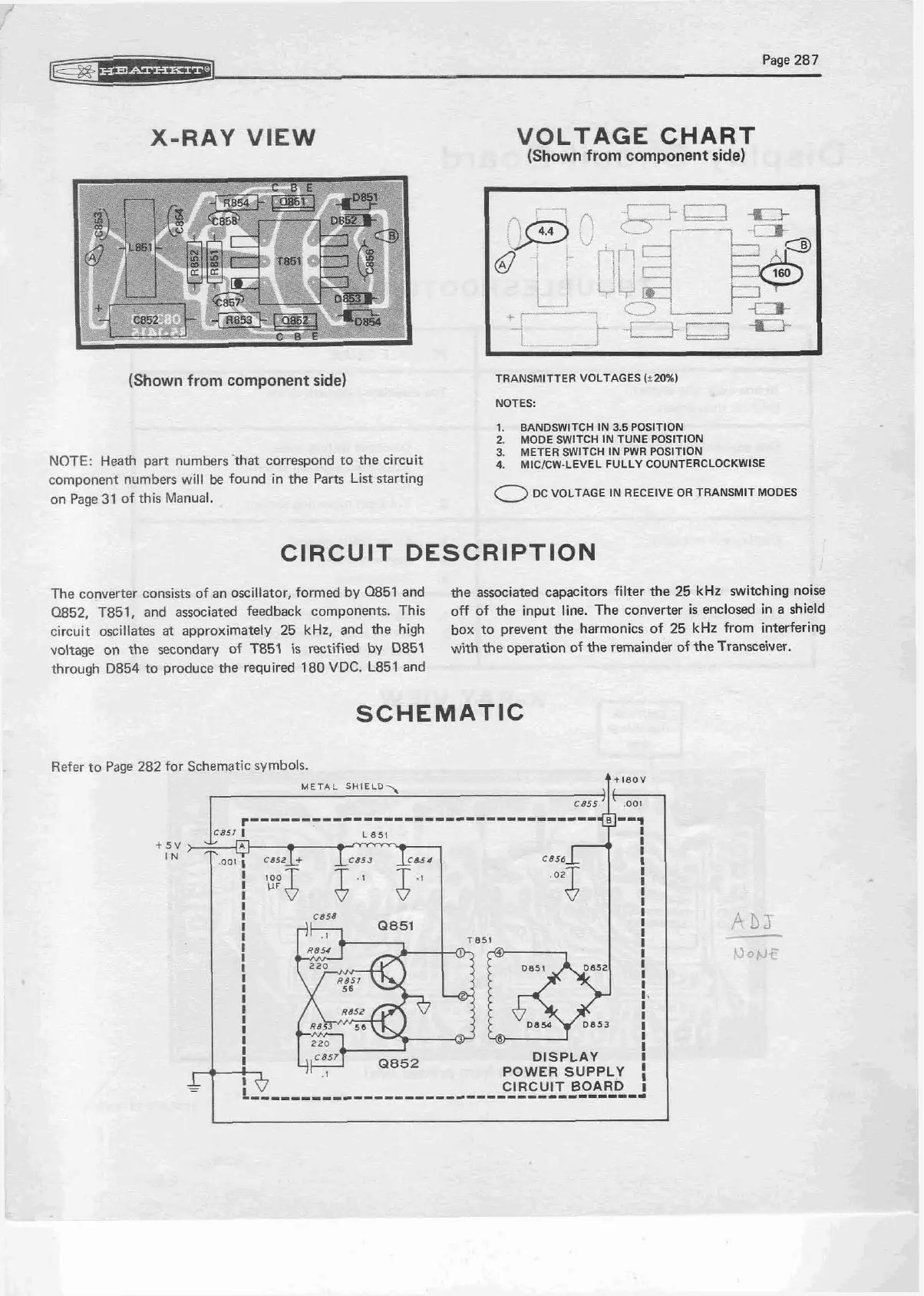
CIRCUIT DESCRIPTION
The converter consists of an oscillator, formed by
0851
and
the associated capacitors filter the
25
kHz switching noise
0852, T851,
and associated feedback components. This
off of the input line. The converter is enclosed
in
a shield
circuit oscillates
at
approximately
25
kHz,
and the high
box to prevent the harmonics of
25
kHz from interfering
voltage on the secondary of
T851 is rectified by
0851
with
the operation of the remainder
of
theTransceivw.
through
D854
to produce the required
180 VDC. L851
and
SCHEMATIC