Page 289
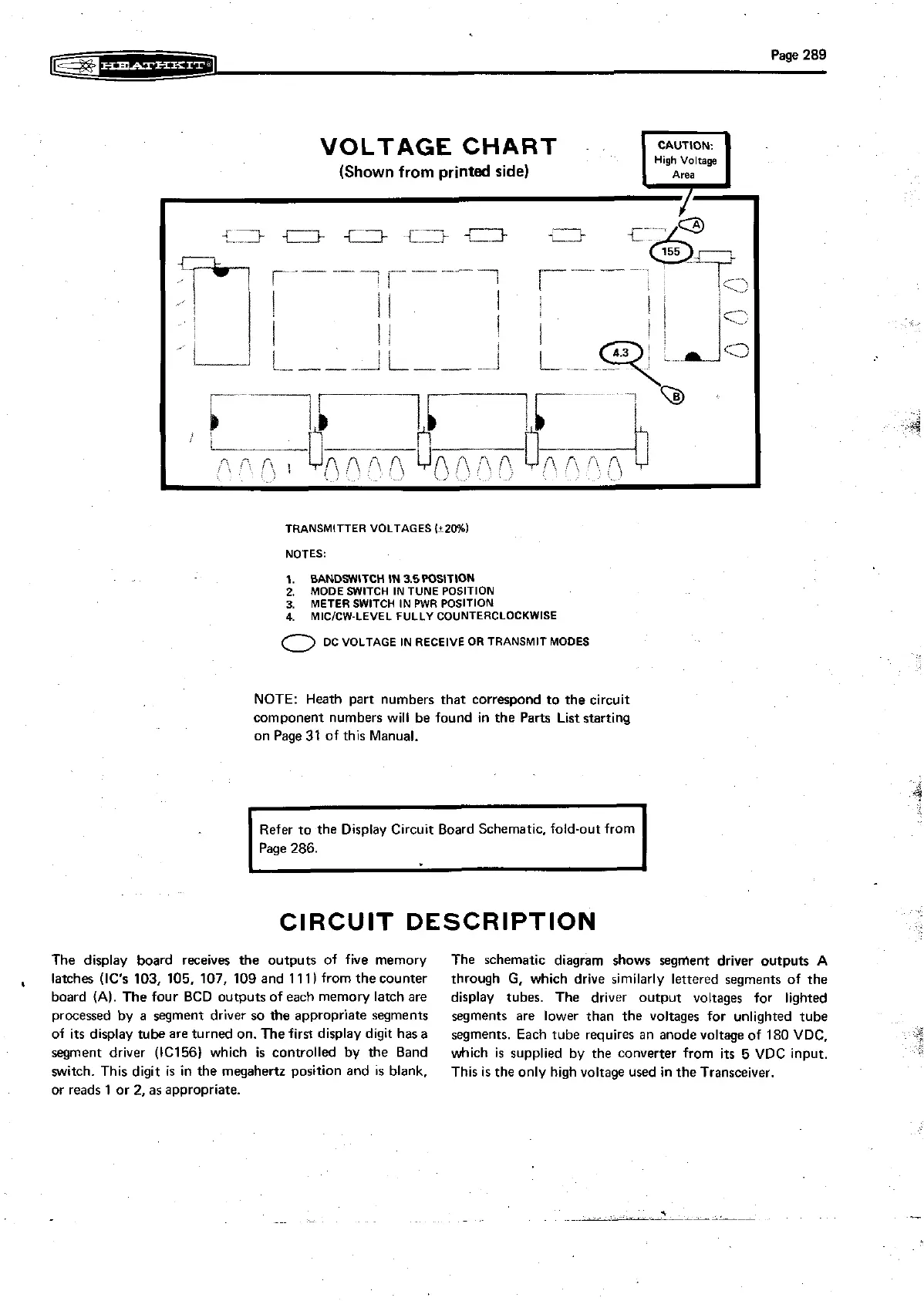
TRANSMITTER
VOLTAGES
I+ZO%l
NOTES:
1.
BANDSWITCH IN 3.5WSITlON
2.
MODE
SWITCH
IN
TUNE
POSITION
3.
METER
SWITCH
IN
PWR
POSITION
4.
MICICW-LEVEL
FULLY
COUNTERCLOCKWISE
0
OC
VOLTAGE
IN
RECEIVE
OR
TRANSMIT
MODES
NOTE: Heath part numbers that correspond to the circuit
component numbers will be found in the Parts Liststarting
on Page
31
of this Manual.
Refer to the Display
Circuit Board Schemat~c, fold-out from
Page 286.
CIRCUIT DESCRIPTION
The display board receives the outputs of five memory The schematic diagram shows segment driver outputs
A
,
latches (IC's 103, 105, 107, 109 and 11
1
)
from the counter
through
G,
which drive similarly lettered segments of the
board
(A).
The four BCD outputs of each memory latch are display tubes. The driver output voltages for lighted
processed by a segment driver so the appropriate segments
segments are lower than the voltages for unlighted tube
of
its
display tube are turned on. The firs display digit hasa
segments. Each tube requires an anode voltage of 180
VDC.
segment driver (IC156l which
is controlled by the Band
which
is
supplied by the converter from
its
5 VDC input.
witch. This digit
is
in the megahertz position and is blank.
This
is
the only high voltage used in the Transceiver.
or reads 1 or
2,
as appropriate.