Page 292
I~b=*='--*=*:*91
CIRCUIT DESCRIPTION
+5VDC-416
SEGMENT DRIVER
lCL5l
I
.
+5v~cl14 COUNTER
1
IC102
MEMORY LATCH PINS
VALUE
H L
H H
6 HHL
1
HHH
8
HLL
P
H H
MEMORY LATCH TRUTH TABLE
L-
LESS THAN O.8VDC
H-
MORE THAN 1.5VOC
Figure
4-4
10000.0 kHz FALSE ZERO FREQUENCY
3393.6
kHz
LSB BF0 FREQUENCY
6606.4 PRESET FREQUENCY
BFO
-
PRESET
US6
3396.4 kHz 6603.6 kHz
LSB 3393,
6
6606.4
C
W
3395
1
6604.3
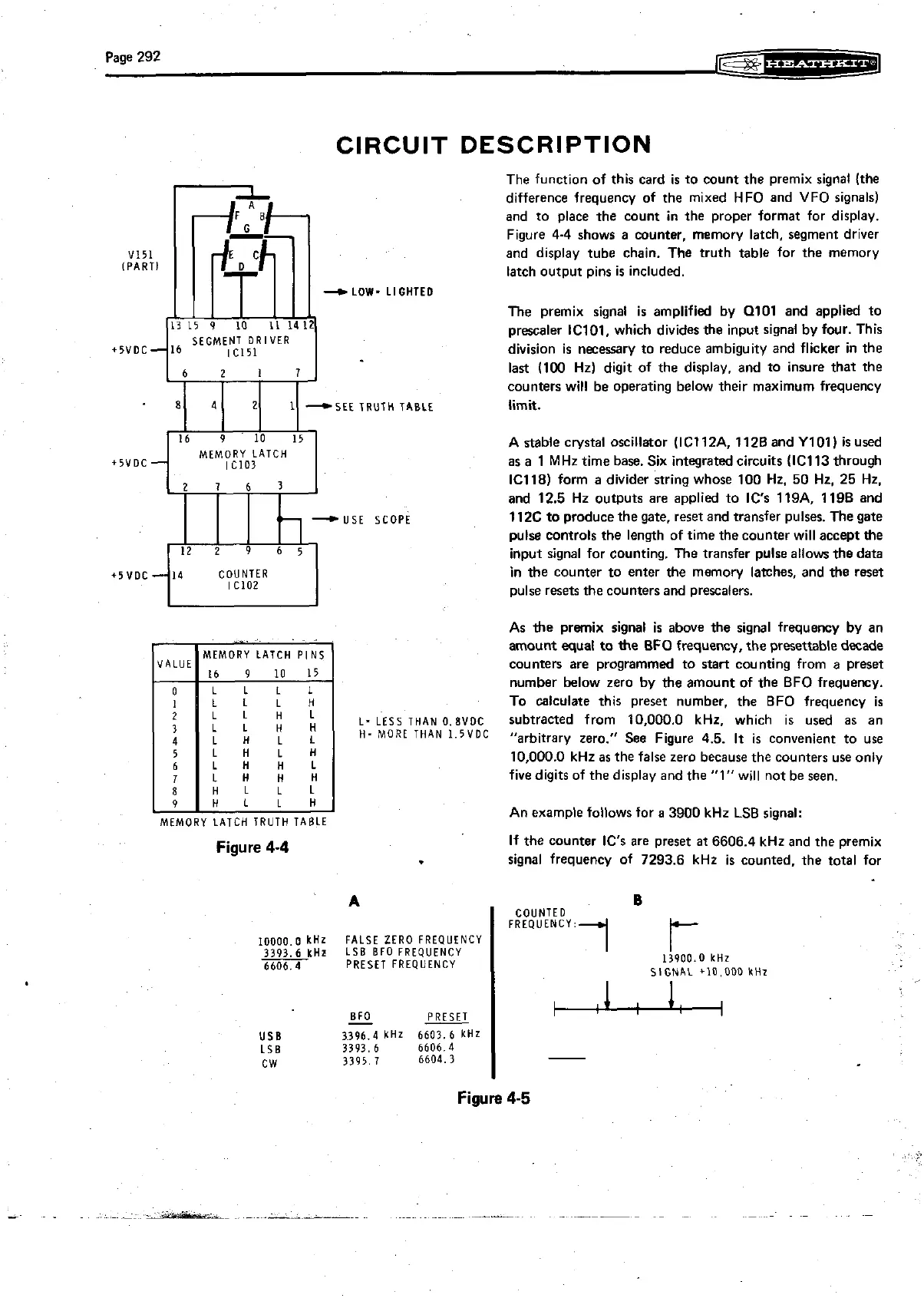
The function of this card
is
to munt the premix signal (the
difference frequency of the mixed HFO and VFO signals)
and to place the
munt in the proper format for display.
Figure
4-4 shows a counter, memory latch, segment driver
and display tube chain. The truth table for the memory
latch output pins
is
included.
The premix signal is amplified by
0101 and applied to
prescaler IC101, which divides the input signal by four. This
division is necessary to reduce ambiguity and flicker in the
last (100 Hz) digit of the display, and to insure that the
counters will be operating below their maximum frequency
limit.
A stable crystal oscillator
(IC112A. 1128 and Y101)
is
used
as a
1
MHz time base. Six integrated circuits (IC113 through
IC118) form a divider string whose 100 Hz. 50 Hz. 25 Hz.
and 12.5 Hz outputs are applied to
IC's 119A. 1198 and
112C to produce the gate, reset and transfer pulses. The gate
pulse controls the length of time the counter will accept the
input signal for counting. The transfer pulse allows the data
in the counter to enter the memory latches, and the reset
pulse resets the counters and
prescalers.
As the premix signal is above the signal frequency by an
amount equal to the BFO frequency, the presettable decade
counters are programmed to start counting from a preset
number below zero by
the amount of the BFO frequency.
To calculate this preset number, the BFO frequency
is
subtracted from 10.000.0 kHz, which is used as an
"arbitrary zero." See Figure 4.5.
It
is
convenient to use
10,000.0 kHz as the false zero because the counters use only
five digits of the display and the
"1" will not be seen.
An example follows for a 3900 kHz LSB signal:
If
the counter IC's are preset
at
6606.4 kHz and the premix
signal frequency of 7293.6 kHz
is
counted, the total for
Figure
4-5