(
)
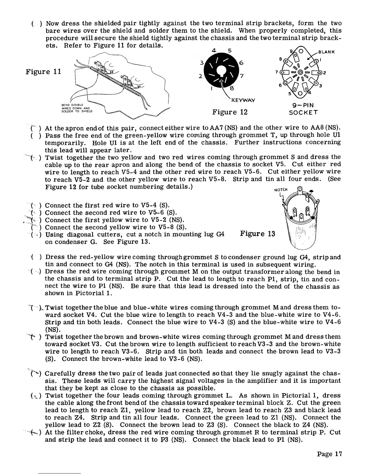
Now
dress
the
shielded
pair tightly
against
the two
terminal
strip brackets,
form
the two
bare
wires
over the
shield
and
solder
them
to the shield. When properly
completed,
this
procedure will
secure the
shield tightly against
the
chassis and
the
two
terminal strip
brack-
ets.
Refer
to Figure 11 for details.
KEYWAY
Figure
12
9—
PI
N
SOCKET
( )
At
the
apron
end
of this
pair,
connect either
wire toAA7
(NS)
and the
other
wire to
AA8(NS).
( )
Pass
the
free
end
of
the
green-yellow
wire
coming
through
grommet
T,
up
through
hole
Ul
temporarily.
Hole
Ul
is
at
the
left end
of
the chassis.
Further
instructions
concerning
this lead
will
appear
later.
t )
Twist
together the
two
yellow and two
red
wires
coming through
grommet
S
and dress
the
cable up to
the
rear
apron and
along
the bend
of
the chassis
to
socket
V5.
Cut
either
red
wire
to length to
reach
V5-4
and
the other
red
wire to
reach
V5-6.
Cut
either
yellow wire
to reach
V5-2
and
the
other yellow
wire
to reach
V5-8.
Strip
and
tin
all four ends. (See
Figure 12 for tube
socket
numbering
details.)
( )
Connect the
first
red
wire
to
V5-4
(S).
(
)
Connect the
second
red wire to
V5-6 (S).
^
)
Connect
the first
yellow wire
to
V5-2
(NS).
('
)
Connect the
second
yellow wire
to
V5-8 (S).
(
)
Using
diagonal
cutters,
cut
a
notch in mounting
lug
G4
Figure
13
on condenser
G.
See
Figure 13.
(
)
Dress the
red-yellow
wire coming
through grommet
S
to condenser
ground lug
G4,
strip
and
tin
and
connect
to
G4
(NS).
The
notch
in
this
terminal
is used
in
subsequent wiring.
(
)
Dress the red
wire coming
through
grommet
M
on the
output
transformer
along
the
bend in
the chassis
and
to terminal
strip
P. Cut the
lead
to
length
to reach
PI, strip, tin
and
con-
nect
the wire to
Pi
(NS). Be
sure that
this
lead is
dressed
into
the
bend of
the
chassis
as
shown in
Pictorial
1.
X
)-
Twist
together the
blue and blue-white wires
coming through
grommet
Mand
dress them to-
ward
socket
V4.
Cut the
blue wire
to length
to
reach
V4-3
and
the
blue-white wire
to
V4-6.
Strip
and
tin
both
leads.
Connect the blue wire to
V4-3 (S)
and the blue-white wire
to
V4-6
(NS).
X*
)
Twist
together the
brown and brown-white
wires coming through
grommet
M
and dress
them
toward
socket
V3.
Cut
the brown
wire
to length
sufficient
to reach
V3-3
and
the
brown-white
wire
to
length to
reach
V3-6.
Strip
and tin both leads and connect
the
brown lead
to
V3-3
(S).
Connect
the
brown-white lead to
V3-6
(NS).
("'*)
Carefully
dress
the
two pair
of
leads just connected so that they
lie snugly against the chas-
sis. These
leads
will
carry the highest signal
voltages
in the amplifier
and
it is
important
that they
be
kept as close
to
the
chassis
as
possible.
(
O
Twist
together
the
four
leads coming through grommet
L.
As
shown
in
Pictorial
1,
dress
the
cable along
the front
bend
of the
chassis
toward speaker
terminal block
Z.
Cut the
green
lead
to length
to reach
Zl,
yellow
lead
to reach
Z2,
brown lead
to reach
Z3
and
black lead
to reach
Z4.
Strip
and
tin all
four leads. Connect
the
green
lead
to Zl
(NS).
Connect the
yellow lead
to
Z2
(S).
Connect
the brown
lead
to
Z3
(S).
Connect the black to
Z4
(NS).
(•»-.)
At
the filter choke,
dress
the
red wire
coming through grommet
R
to
terminal strip
P.
Cut
and strip
the lead
and
connect
it
to
P3
(NS).
Connect the black
lead to
PI
(NS).
Page 17