The Heathkit Model TA-16 Guitar Amplifier is a solid-state electronic product designed for use with electric guitars and other musical instruments equipped with electric pickups. It offers a range of features for modern guitarists, including high-power amplification, special effects, and versatile control options.
Function Description:
The amplifier features two independent channels: a Normal Channel and a Reverb Channel. Each channel provides two inputs, along with Volume, Bass, and Treble controls, allowing for a wide range of tonal adjustments.
The Normal Channel is typically used for accompaniment instruments or microphones, offering a clean amplified sound. Its preamplifier circuit, consisting of transistors Q1 and Q3, processes input signals through isolation resistors, mixing them before amplification. Tone compensation is achieved through Bass and Treble controls, which utilize out-of-phase feedback to either cut or boost frequencies. Capacitor C101 and C3 limit the effect of the Bass control to lower frequencies, while capacitor C4, with its low value, blocks low frequencies for the Treble control.
The Reverb Channel is designed for lead instruments and incorporates special effects: reverb and tremolo. Reverb intensity and both the depth and rate of the tremolo are adjustable. Foot switches are provided for hands-free control of these effects. The Reverb Channel's preamplifier circuit, utilizing transistors Q2 and Q4, is identical in operation to the Normal Channel's tone control network. The output signal from the second preamplifier transistor Q4 splits into two paths: one to the mixer transistor Q6 and another to the reverb driver transistor Q11.
The reverb delay circuits amplify the Reverb Channel signal via transistor Q11 and then couple it to the reverberation unit. This unit, comprising two transducers and two delay springs, converts the electrical signal into physical motion, which is slightly delayed as it travels through the springs. The output transducer then converts this motion back into an electrical signal, which is coupled to the Reverb control. The Reverb control determines the amount of this delayed signal mixed into the main signal path. Transistor Q5 amplifies the delayed signal, and its base is connected to a foot switch, allowing the reverb effect to be turned on or off by grounding the base bias.
The tremolo circuit utilizes a Light Dependent Resistor (LDR) as its output element. A subsonic, phase-shift oscillator circuit, driven by transistor Q12, generates a signal with a variable frequency (4 to 14 Hz), controlled by the Rate knob. The amplitude of this oscillator signal is varied by the Depth control and then coupled to the tremolo modulator transistor Q13. Transistors Q12 and Q13 are connected to a common emitter resistor for positive feedback. The LDR unit consists of a low-current lamp and a light-dependent resistance element. As transistor Q13 amplifies the tremolo oscillator signal, its collector current modulates the lamp's brightness, causing the LDR's resistance to vary. This resistance variation, from a very low to a very high value, modulates the Reverb Channel signal, creating the tremolo effect. The tremolo circuit can also be turned on or off via the foot switch, which shorts the base of oscillator transistor Q12 to ground when in the Off position.
Both the Normal and Reverb Channel signals are combined at the base of the mixer amplifier transistor Q6. The combined signal is then amplified by Q6, predriver transistor Q7, and driver transistor Q8. The amplified signal from Q8's collector is coupled to the output transistors Q9 and Q10. Diode D101, part of Q8's collector load, sets the base bias for the output transistors and provides temperature stability. Output transistors Q9 (PNP) and Q10 (NPN) are configured in a complementary symmetry, class B emitter-follower circuit. They drive the speaker voice coils, converting the electrical signal back into sound.
A line-reversing Off-On switch ensures minimum hum by allowing either side of the power line to be connected to the chassis through capacitor C103. All controls and inputs are conveniently located on the top-front control panel.
Important Technical Specifications:
- Power Output:
- Peak Power Output: 60 watts
- Music Power Output: 25 watts*
- Continuous Power Output: 20 watts*
- Rated EIA (Electronics Industries Association) standards.
- Damping Factor: 50 or better
- Hum And Noise (inputs open):
- Normal Channel: -55 db below 25 watts
- Reverb Channel: -60 db below 25 watts
- Input Sensitivity (25 watts output):
- Normal Channel: 25 millivolts
- Reverb Channel: 35 millivolts
- Input Impedance:
- Normal Channel: 25 K ohms (each input)
- Reverb Channel: 25 K ohms (each input)
- Reverb Level: Variable
- Reverb Delay:
- Long Spring: .037 seconds (nominal)
- Short Spring: .029 seconds (nominal)
- Tremolo Speed: Variable from 4 to 14 hertz
- Tremolo Depth: Variable from 0 to approximately 75% amplitude modulation
- Speakers: Two 12" special design with ceramic magnet
- Transistor Complement:
- 3 x 2N3391 (first normal preamplifier, first reverb preamplifier, reverb amplifier)
- 3 x 2N3393 (second normal preamplifier, second reverb preamplifier, mixer amplifier)
- 1 x 2N3566 (reverb driver)
- 1 x 2N3692 (tremolo oscillator)
- 1 x S2090 (tremolo modulator)
- 1 x 2N3416 (predriver)
- 1 x 2N3053 (driver)
- 1 x 2N2148 (output amplifier)
- 1 x TA2577A (output amplifier)
- Diode Complement:
- 1 x 1N3754 (reference diode)
- 4 x Bridge rectifiers
- 1 x 13 volt zener diode
- Circuit Breakers: One primary and one secondary; each 2.11 amperes.
- AC Power Socket: 120 VAC, 200 watts.
- Inputs:
- Normal Channel: 2 inputs
- Reverb Channel: 2 inputs
- Controls:
- Normal Channel: Volume, Bass, Treble
- Reverb Channel: Volume, Bass, Treble, Tremolo Rate, Tremolo Depth, Reverb Level
- Line Reverse: On-Off-On switch
- Power Requirements: 105-125 volts or 210-250 volts, 50-60 hertz, 15 watts idling and 60 watts at full output.
- Cabinet: 3/4" wood with black Lavant covering. 28" wide x 9" deep x 19-3/4" high (including carrying handle).
- Net Weight: 41 pounds.
- Accessory (Included With Amplifier): Foot switch: Reverb On-Off; Tremolo On-Off.
Usage Features:
- Versatile Instrument Compatibility: Designed for Harmony-by-Heath and other high-quality Electric Guitars, it can also be used with accordions and other musical instruments with electric pickups.
- Dual Channels: Two distinct amplifier channels allow for separate processing of lead instruments (with effects) and accompaniment instruments/microphones.
- Comprehensive Tone Shaping: Each channel includes Volume, Bass, and Treble controls for detailed sound customization.
- Special Effects: The Reverb Channel offers adjustable reverb and tremolo (depth and rate) for enhanced sound.
- Hands-Free Control: Foot switches enable convenient on/off control of reverb and tremolo during performance.
- Hum Reduction: A line-reversing Off-On switch helps minimize unwanted hum.
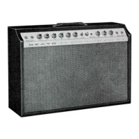
- Durable and Attractive Design: The amplifier features a black, leather-textured cabinet and a black-and-white patterned grille cloth, ensuring both durability and aesthetic appeal.
- Convenient Control Placement: All controls and inputs are located on the top-front control panel for easy access.
- Power Transformer Versatility: The power transformer can be wired for either 105-125 volt or 210-250 volt AC operation, adapting to different line voltages.
Maintenance Features:
- Kit Assembly: The product is provided as a kit, allowing users to build and understand the amplifier's internal workings.
- Detailed Assembly Manual: The manual includes step-by-step instructions, pictorials, and a "Kit Builders Guide" for unpacking, parts identification, tools, wiring, and soldering.
- Troubleshooting Chart: A comprehensive chart helps diagnose common issues, linking symptoms to possible causes and recommended solutions.
- Initial Test Procedure: An initial test section guides users through visual inspections and resistance checks to ensure proper assembly before first operation.
- Voltage Chart and Schematic Diagram: These resources aid in advanced troubleshooting by providing expected voltage readings and circuit details.
- Testing Precautions: Warnings are provided regarding short circuits, voltage measurements, and handling transistors to prevent damage during testing.
- Circuit Breakers: Two circuit breakers (primary and secondary) protect the amplifier from overloads, with a procedure outlined for resetting them.
- Point-to-Point Hum Test: A specific test procedure helps locate sources of hum within the amplifier.
- Signal Tracing: Instructions for using a signal tracer or oscilloscope to identify points of signal loss are provided.
- Replacement Parts Price List: A list of replacement parts with their prices is included, along with instructions for ordering.
- Factory Repair Service: Heath Company offers repair services for completed kits, with clear instructions for returning equipment for service.
- Warranty: A 90-day warranty covers defective parts and necessary repairs, with after-warranty service also available.