01-02 9 28466 Rev H
NOVUS B-VENT INSTALLATION INSTRUCTIONS
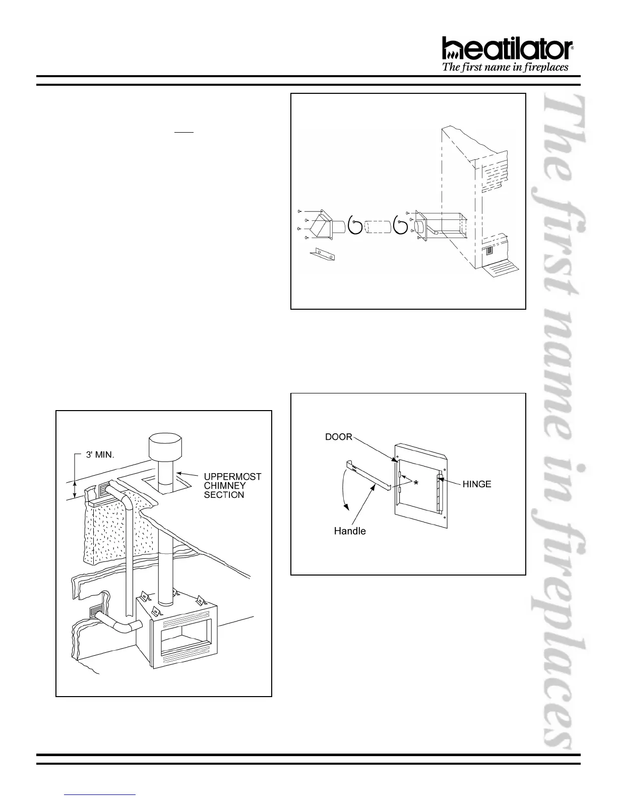
a. The air kit can only be installed on the left side of
the appliance. See Figures 10 and 11 for correct
orientation of the door assembly and handle. The
hinge will be toward the back of the appliance.
b. Remove the cover plate or knockout from the side
of the appliance and discard.
c. Partly open the air kit door. The hinge on the door
assembly should be located toward the back of
the appliance. If the hinge is not positioned in
this manner, the door will not function correctly.
d. Attach the door assembly to the appliance using
the screws provided.
e. Bend down the left tab on the lower left glass
retainer. Insert the narrow end of the handle
through the tab and into the upper slot on the air
kit door.
f. Check operation by pulling the handle out to open,
and pushing it in to close.
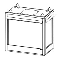
g. Mark and cut a hole in the building side for air
entry. This hole should allow some framing (two
sides) so the inlet tube assembly may be
fastened properly.
h. Assemble the flexible duct (not supplied) between
the door assembly and the inlet tube assembly.
Secure it in position with the supplied wire ties.
Figure 9 - Outside Air Locations
Figure 10 - Air Kit Installation
Figure 11 - Air Kit Door Assembly & Handle
 Loading...