28466 Rev H 10 01-02
NOVUS B-VENT INSTALLATION INSTRUCTIONS
F. UTILITIES
1. HIGH ALTITUDE INSTALLATION
For U.S. installation, appliances are tested and approved for elevations from 0-2000 feet. When installing this
appliance at an elevation above 2000 feet, National Fuel Gas Codes require a decrease of the input rating by
changing the existing burner orifice to a smaller size. Input should be reduced 4% for each 1000 feet above sea
level. Check with the local gas utility for proper orifice size identification. Orifices are available from your distributor.
For Canada, appliances are certified for elevations from 0-4500 feet. When installing this appliance at an elevation
between 0-4500 feet in Canada, the input rating does not need to be reduced. When installing this appliance at an
elevation above 4500 feet in Canada, check with local authorities.
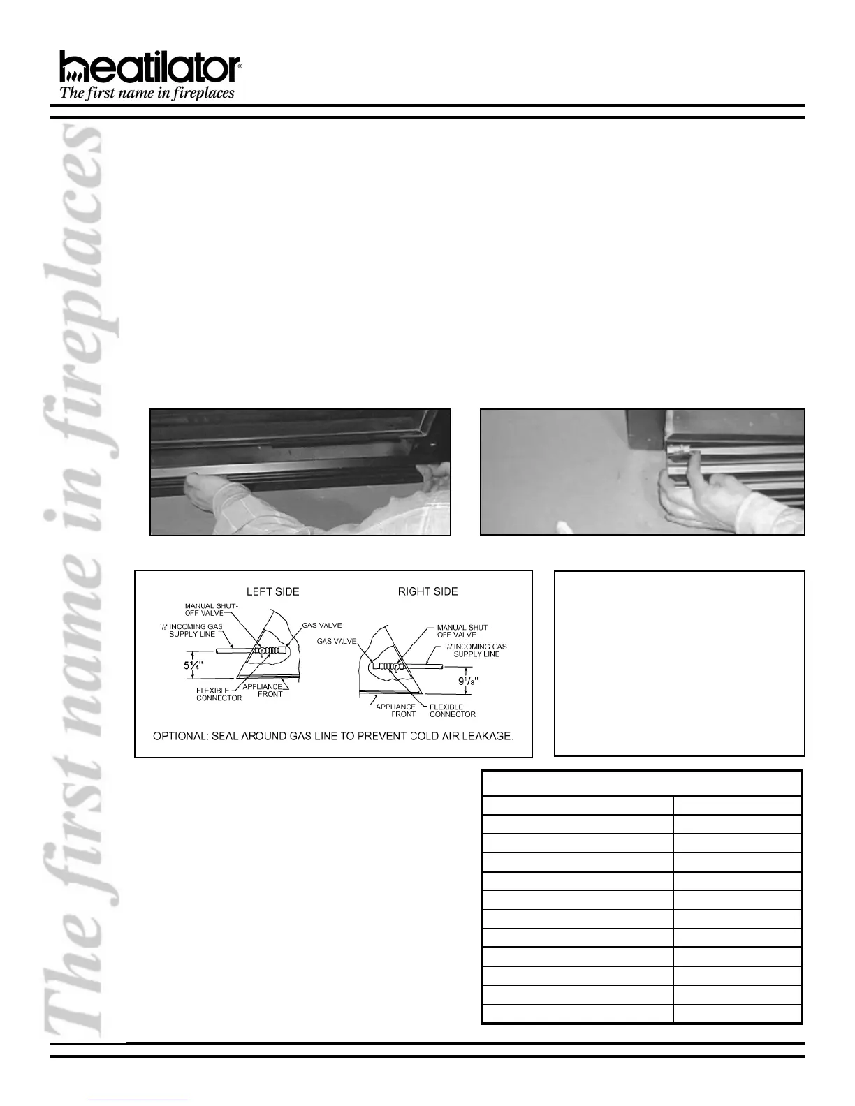
2. GAS LINE CONNECTION
Open the control access panel as shown in Figures 12 and 13. The appliance is provided with a stainless steel
flexible connector and manual shutoff valve. The incoming gas line should be piped into the valve compartment and
connected to the 1/2 FIP connection provided on the manual shutoff valve. See Figure 14. All connections must be
tightened and checked for leaks with a soap water solution or leak detector. Bleed the gas line to extract any air that
may have been trapped inside the pipe.
Figure 12 - Control Access Panel Removal Figure 13 - Control Access Panel Removal
Note: The appliance and its individual
shutoff valve must be disconnected from
the gas supply piping system during any
pressure testing of that system at test pres-
sures in excess of 1/2 psi (3.5 kPa). The
appliance must be isolated from the gas
supply piping system by closing its indi-
vidual manual shutoff valve during any pres-
sure testing of the gas supply piping sys-
tem at test pressures equal to or less than
1/2 psi (3.5 kPa).
Figure 14 - Gas Line
3. GAS PRESSURE
On the standing pilot gas control valve and the
electronic valve, a pressure tap is included on the
front face of the valve.
Table 2 shows optimum gas pressure information.
(The * designates measurement in inches/water
column.)
Consult your local gas company for assistance in
determining the proper orifice for your altitude or refer
to ANSI Z223.1-latest edition, Appendix F.
Table 2
SUVON
.G.N-erusserpylppuSsagtelnI*).xaM(0.7-).niM(5.4
.G.N-erusserpdlofinaMmumitpO*5.3
.P.L-erusserpylppuSsaGtelnI*).xaM(0.41-).niM(0.11
.P.L-erusserpdlofinaMmumitpO*0.01
.G.N-etaRtupnI03CBNG.rh/UTB000,52
33CBNG.rh/UTB000,52
63CBNG.rh/UTB000,72
.P.L-etaRtupnI63/33CBNG.rh/UTB000,52
03CBNG.rh/UTB000,42
.G.N-eziSecifirO63CBNGmm65.2/.ni101.
33/03CBNGmm34.2/.ni690.
.P.L-eziSecifirO
63/33/03CBNG
mm05.1/.ni950.
nmulocretaw/sehcni*
 Loading...