Heatilator • NDV30-IFT, NDV33-IFT, NDV36-IFT, NDV36-IFT-NVR, NDV42-IFT Installation Manual • 2620-980 Rev. C • 8/20
2
Safety Alert Key:
• DANGER! Indicates a hazardous situation which, if not avoided will result in death or serious injury.
• WARNING! Indicates a hazardous situation which, if not avoided could result in death or serious injury.
• CAUTION! Indicates a hazardous situation which, if not avoided, could result in minor or moderate injury.
• NOTICE: Used to address practices not related to personal injury.
Note: The term “recommend” or “recommended” does not indicate a requirement. It is a best practice suggested by Hearth
& Home Technologies
®
. Failure to perform the recommended task will not result in a safety concern.
Table of Contents
Installation Standard Work Checklist .................... 3
1 Product Specic and Important Safety Information
A. Appliance Certication ............................4
B. Glass Specications .............................. 4
C. BTU Specications ............................... 4
D. High Altitude Installations .......................... 4
E. Non-Combustible Materials Specication. . . . . . . . . . . . . . 5
F. Combustible Materials Specication .................5
G. Electrical Codes .................................5
H. California ......................................5
I. Requirements for the Commonwealth of Massachusetts ..6
2 Getting Started
A. Design and Installation Considerations ............... 7
B. Good Faith Wall Surface ..........................7
C. Tools and Supplies Needed ........................7
D. Inspect Appliance and Components ..................8
3 Framing and Clearances
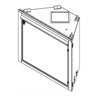
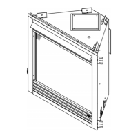
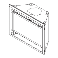
A. Appliance/Decorative Front Dimension Diagrams ....... 9
B. Appliance Location and Clearances to Combustibles ... 13
C. Constructing the Appliance Chase ..................16
4 Termination Location and Vent Information
A. Approved Pipe .................................17
B. Vent Termination Minimum Clearances ..............17
C. Vent Terminal Clearances ........................18
D. Use of Elbows .................................19
E. Vent Diagrams .................................20
5 Vent Clearances and Framing
A. Pipe Clearances to Combustibles .................. 33
B. Wall Penetration Framing/Firestops .................34
C. Ceiling Firestop/Floor Penetration Framing ...........35
D. Install Attic Insulation Shield .......................35
6 Appliance Preparation
A. Vent Collar Preparation ..........................36
B. Prepare For Heat Management ....................38
C. Securing and Leveling the Appliance ................38
7 Venting and Chimneys
A. Assemble Vent Sections (DVP Pipe Only) ...........39
B. Assemble Slip Sections ..........................41
C. Secure the Vent Sections ......................... 41
D. Disassemble Vent Sections .......................42
E. Vertical Termination Requirements ..................42
F. Horizontal Termination Requirements ...............43
G. Shrouds ......................................45
8 Electrical Information
A. General Information .............................46
B. Wiring Requirements ............................47
9 Gas Information
A. Fuel Conversion ................................49
B. Gas Pressure ..................................49
C. Gas Connection ................................49
D. High Altitude Installations ......................... 49
E. Air Shutter Setting ..............................50
10 Finishing
A. Facing Material .................................51
B. Combustible Mantel and Wall Projections ............51
C. Non-combustible Mantel and Wall Projections ......... 52
11 Appliance Setup
A. Remove the Shipping Materials .................... 53
B. Clean the Appliance .............................53
C. Install Optional Refractory Kit ......................53
D. Install Burner Mineral Wool .......................53
E. Install Fixed Glass Assembly ......................54
F. Install Decorative Barrier Front. . . . . . . . . . . . . . . . . . . . . 54
G. Install the Log Assembly. . . . . . . . . . . . . . . . . . . . . . . . . . 55
12 Reference Materials
A. Vent Components Diagrams ......................57
B. Optional Components. . . . . . . . . . . . . . . . . . . . . . . . . . . . 68
C. Accessories ...................................69
= Contains updated information.