7
Heatilator • NDV30-IFT, NDV33-IFT, NDV36-IFT, NDV36-IFT-NVR, NDV42-IFT Installation Manual • 2620-980 Rev. C • 8/20
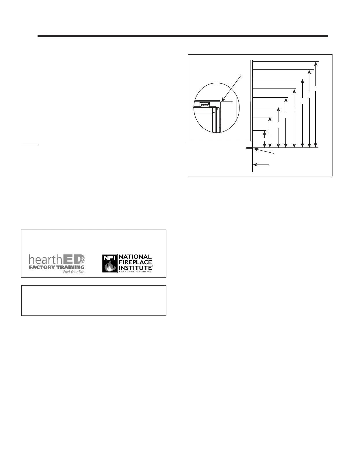
MEASUREMENTS FROM
TOP EDGE OF THE OPENING
6 in.
18 in.
24 in.
30 in.
36 in.
48 in.
42 in.
12 in.
123°F
115°F
120°F
132°F
145°F
170°F
180°F
APPLIANCE FRONT
APPLIANCE OPENING
2 2
Getting Started
A. Design and Installation Considerations
WARNING! Risk of Fire or Explosion! Read all instruc-
tions before starting the installation.
Heatilator direct vent gas appliances are designed to op-
erate with all combustion air siphoned from outside of the
building and all exhaust gases expelled to the outside. No
additional outside air source is required.
Installation MUST comply with local, regional, state and
national codes and regulations. Consult insurance carrier,
local building inspector, re ofcials or authorities having
jurisdiction over restrictions, installation inspection and
permits.
Before installing, determine the following:
• Where the appliance is to be installed.
• The vent system conguration to be used.
• Gas supply piping requirements.
• Provisions for optional heat management system.
• Electrical wiring requirements.
• Framing and nishing details.
• Whether optional accessories—devices such as a fan,
wall switch, or remote control—are desired.
C. Tools and Supplies Needed
Before beginning the installation be sure that the following
tools and building supplies are available.
Hand Tools Tape measure
Level Framing material
Manometer Framing square
Voltmeter Electric drill and bits (1/4 in.)
Plumb line Safety glasses/Gloves
Wrenches Reciprocating saw
1/4 in. nut driver
Non-corrosive leak check solution
1/2 - 3/4 in. length, #6 or #8 Self-drilling screws
1/4 in. length, #6 or #8 Self-drilling screws (B-Vent only)
Caulking material (300 ºF minimum continuous exposure
rating)
Improper installation, adjustment, alteration, service or
maintenance can cause injury or property damage. For
assistance or additional information, consult a qualied
service technician, service agency or your dealer.
Figure 2.1 Good Faith Wall Surface Temperatures Above Appliance
B. Good Faith Wall Surface
NOTICE: Surface temperatures listed above are taken with
a temperature measuring probe as prescribed by the test
standard used for appliance certication. Temperatures
on walls or mantels taken with an infrared thermometer
may yield increased temperatures of up to 30 °F (17 °C) or
more depending on the thermometer settings and material
characteristics being measured. Use appropriate nishing
materials that are able to withstand these conditions. For
additional nishing guidelines, see Section 10.
Installation and service of this appliance should be performed by
qualied personnel. Hearth & Home Technologies recommends
HHT Factory Trained or NFI certied professionals.
If installing a television (TV) above the appliance, see
Section 3 of the appliance Owner’s Manual.
 Loading...