EasyManua.ls Logo

hecht 256 User Manual

hecht 256
24 pages
To Next Page IconTo Next Page
Page #1 background imageLoading...
Page #1 background image
EN
Congratulations on
your purchase of
the product brand
HECHT. Before the first
operation, please read
the owner‘s manual
carefully!
DE
Herzlichen
Glückwunsch zum Kauf
eines HECHT-Produktes.
Bitte lesen Sie diese
Anleitung vor der
ersten Inbetriebnahme
sorgfältig durch!
FR
Nous vous félicitons
d‘avoir acheté un
produit HECHT. Veuillez
lire attentivement ce
manuel avant de le
mettre en service pour
la première fois !
PL
Gratulujemy zakupu
produktu marki
HECHT. Przed
pierwszym użyciem
należy dokładnie
przeczytać instrukcję
obsługi!
HU
Köszönjük Önnek, hogy
megvásárolta a HECHT
márkájú terméket! A
készülék első üzembe
helyezése előtt
figyelmesen olvassa el ezt
a használati utasítást!
256256
DE
ORIGINAL ORIGINAL
ANWEISWUNGENANWEISWUNGEN
HU
EREDETI HASZNÁLATI EREDETI HASZNÁLATI
ÚTMUTA ÚTMUTA
FR
INSTRUCTIONSINSTRUCTIONS
ORIGINALORIGINAL
TŁUMACZENIE TŁUMACZENIE
ORYGINALNEJ ORYGINALNEJ
INSTRUKCJI OBSŁUGIINSTRUKCJI OBSŁUGI
PL
EN
ORIGINAL ORIGINAL
INSTRUCTIONS INSTRUCTIONS
FOR USE FOR USE
Question and Answer IconNeed help?

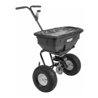
Do you have a question about the hecht 256 and is the answer not in the manual?

hecht 256 Specifications

General IconGeneral
Brandhecht
Model256
CategoryLawn and Garden Equipment
LanguageEnglish

Summary

Step 1: Install the Wheel

Axle Bushing Installation

Instructions for inserting inner and outer axle bushings into the axle.

Wheel and Spacer Installation

Guide for fitting the wheel and spacer onto the axle assembly.

Cotter Pin Installation

Details on installing and securing the Ø5x35 cotter pin into the axle head.

Step 2: Assemble Support Leg

Frame Tube Assembly

Instructions for assembling the main frame tubes and support leg components.

Step 3: Install the Hopper

Axle Insertion into Hopper Base

How to insert the axle head into the bottom hole of the hopper.

Hopper Attachment to Frame

Method for securing the hopper to the tube assembly using bolts, washers, and nuts.

Step 4: Adjust the Handle

Step 5: Assemble Handle and Support Leg

Handle and Support Leg Components

Steps for assembling the handle and support leg using various parts.

Step 6: Assembly Rods

Adjusting Handle Position

Instructions on setting the handle to the desired low position for operation.

Installing Control Rods and Nuts

Steps for installing the connecting rods and securing them with nuts and washers.

Step 7: Adjustment

Safety Symbols Explained

Safety Instructions

General Safety Guidelines

Provides overarching safety precautions for using the equipment safely.

Device-Specific Safety

Detailed safety rules for operating the spreader, including user restrictions and chemical handling.

Operation and Hints

Maintenance and Service

Related product manuals