28 / 56
PL
SK
DE
EN
CS
HU
UNPACKING
• Carefully check all parts after unpacking the product from the box.
• Do not throw away packaging materials until you have not reviewed carefully if they did not
remain a part of the product.
• Parts of the packaging (plastic bags, paper clips, etc.) do not leave within reach of children,
could be a possible source of danger. There is a danger of swallowing or suffocating!
• If you notice transport damage or while unpacking, notify your supplier immediately. Do not
operate the product!
• We recommend save the package for future use. The packaging materials must still be
recycled or disposed of in compliance with the relevant legislation. Sort different parts of
the packaging according to material and hand it to the appropriate collection sites. For
further information contact your local administration.
PACKAGE CONTENTS
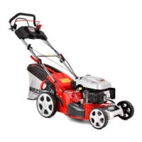
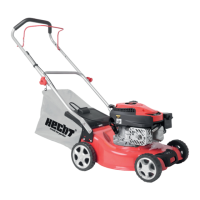
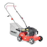
1x lawn mower body, 1x upper part of the handle, 1x lower part of the handle, 1x grass catcher,
1x handle for the grass catcher, 1x front wheel cover, 1x front caster wheel, 1x mulching wedge,
1x discharge channel, 1x spark plug wrench, 1x manual for use
Standard accessories are subject to change without notice.
ASSEMBLY
This product requires assembly. The device must be assembled correctly before use.
The complete push bar, the grass catcher and the wheels must be assembled before using
the lawnmower. Follow the operating instructions step-by-step and use the pictures provided as
a visual guide to easily assemble the machine.
FOLDING HANDLE
1. Use the knob with wing nut and with washer to fix the lower handlebars into the mower
body (fig. 2).
2. Lift the two locking levers to release the upper handlebars for folding (fig. 3A).
3. Push the locking lever closed to lock the handlebars (fig. 3B, C) in the operating position
(fig. 4).
4. Eventually adjust the tension by turning the lock nut with a suitable spanner (fig. 3D).
5. Attach the cable using the cable-clamp (fig. 5).
ADJUSTMENT FOR AN APPROPRIATE ANGLE
1. Pull the locking lever opening.
2. Rotating the upper handle centered of the angle adjusting gear for adjusted a appropriate
angle (fig. 4) into the scope – 20º to +20º (5 position: – 20º/-10º/0º/+10º/+20º).
3. Push the locking lever closed to connect the lower handle and the upper handle.
ASSEMBLE THE FRONT WHEEL
1. Fix the front caster wheel cover into the holder body with bolts and washers (fig. 6).
2. Fix the front wheel holder into the deck body with three hexagon bolts and hexagon locking
nuts (fig. 7).
3. Attach the cable-clamp on the deck to the position shown and then attach the cable
(fig. 8A).


 To Next Page