109
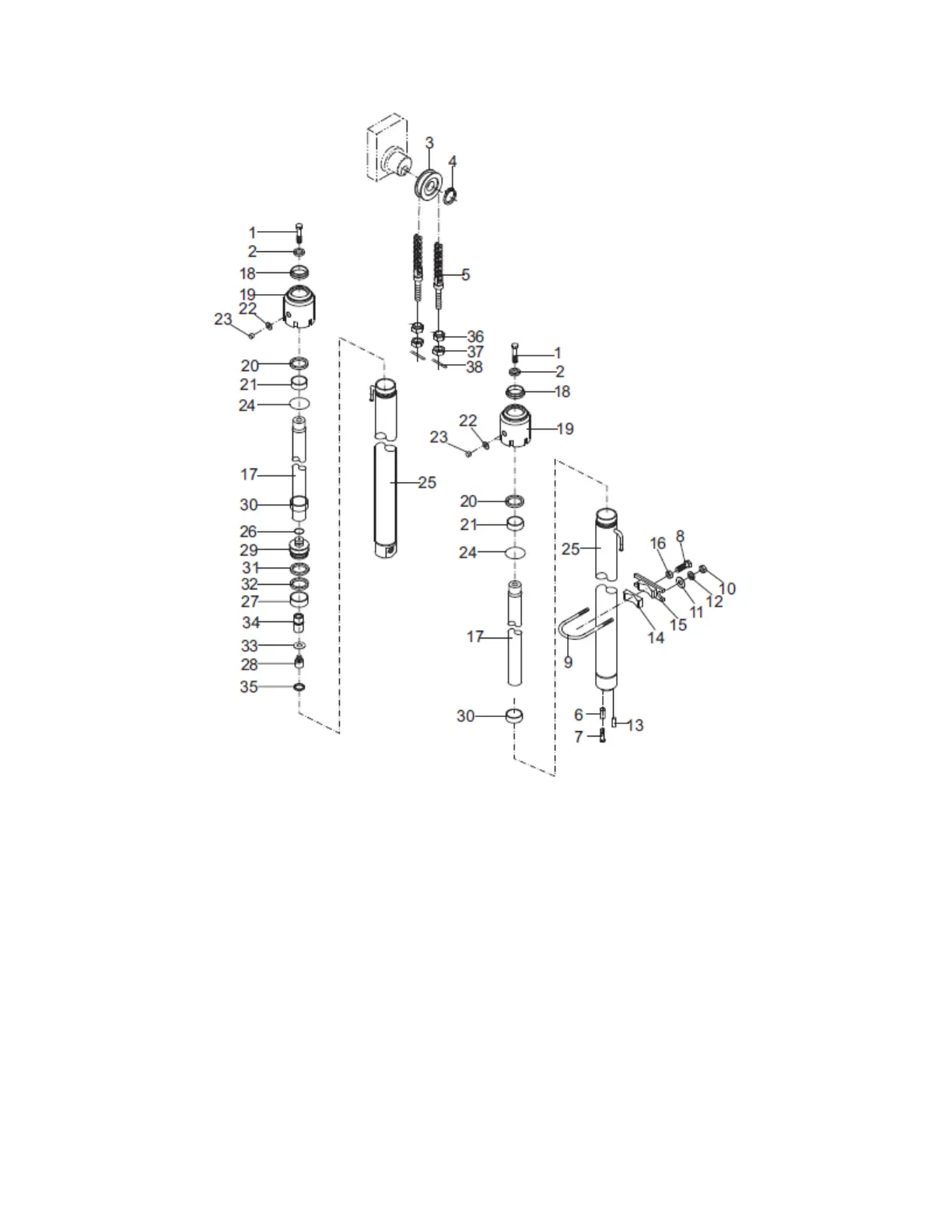
Fig. 5-16 Lift cylinder
1. Bolt M16×1.5×40 2.washer 16 3.chain wheel 4. Snap ring 40
5. Chain wheel assembly 6.spacer bush 7. Bolt M12×1.25×25
8. Bolt M12×1.25×50 9.U type bolt 10.Nut M10×1.25 11.waher 10
12.washer 10 13. Pin B10×26 14. Adjusting block 15.Oil cylinder support block
16. Nut M12×1.25 17.Piston rod 18.dust proof ring 40×52×7/10 19.guide sleeve
20. Seal ring 40×50×6 21. Steel-backed bearing 4030 22.Shim 23. Screw M5×6
24. O ring d49.7×2.4 25. Cylinder body 26. Steel cable baffle ring
27.support ring 50×10×2.5 28. Valve assembly 29. Piston
30. Adjusting sleeveφ48×40.5 31.retaining plate 50×40×3
32.seal ring for hole 50×40×6 33.shim 34.sleeve 35.steel-cable baffle ring for hole
36.Spherical nut 37. Nut M14×1.5 38. Pin 3.2×30