24
Initial start-up and functions
7
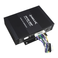
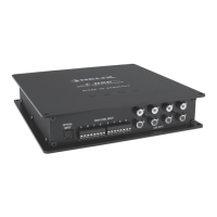
Power Input
This input is used for connecting the signal pro-
cessor to the power supply of the vehicle and for
remote in / out. If the highlevel loudspeaker inputs
are used the remote input can be left unconnected.
The remote output is used for turning on / o ampli-
ers that are connected to the Line Outputs of the
HELIX DSP ULTRA. Connect this remote output to
the remote inputs of your amplier/s. This is essen-
tial to avoid any interfering signals.
The remote output is activated automatically as
soon as the booting process of the DSP is complet-
ed. Additionally this output will be turned o during
the “Power Save Mode” or a software update pro-
cess.
Attention: Solely use the pluggable screw-terminal
which is included in delivery to connect the HELIX
DSP ULTRA to the power supply!
Important: Never use a dierent signal than the
remote output of the DSP to activate connected
ampliers!
8
Control pushbutton
The DSP ULTRA provides 10 internal memory lo-
cations for sound setups. The Control pushbutton
allows the user to switch between two memory po-
sitions. These can be dened in the DSP PC-Tool.
Pressing the button for ve seconds completely
erases the internal memory. This is indicated by a
continuous red glowing and constant green ashing
of the Status LED.
Note: The memory locations one and two are de-
ned ex works. To manually switch between the
setups the button has to be pressed and held for
one second. Switching is indicated by a single red
ash of the Status LED. To switch between all inter-
nal memory locations, the optionally available DI-
RECTOR display remote control or the HELIX WIFI
CONTROL is recommended.
Attention: After erasing the setups from memory
the HELIX DSP ULTRA will not reproduce any au-
dio output.
9
Status LED
The Status LED indicates the operating mode of the
signal processor and of its memory.
Green: DSP is ready for operation.
Orange: Power Save Mode is active.
Red: Protection Mode is active. This may have
dierent root causes. The HELIX DSP ULTRA is
equipped with protection circuits against over- and
undervoltage as well as overheating. Please check
for connecting failures such as short-circuits or oth-
er wrong connections.
If the DSP is overheated the internal temperature
protection switches o the remote and signal output
until it reaches a safe temperature level again.
Red / green slow ashing: No operating software
installed. Connect the signal processor to the
DSP PC-Tool software and conrm the automat-
ic update of the operating system. You will nd
the latest version of the DSP PC-Tool software at
www.audiotec-scher.com.
Red / green fast ashing: The currently selected
Sound Setup memory is empty. A new setup has to
be loaded via the DSP PC-Tool software or switch
to a memory position with existing sound setup.
10
USB input
Connect your personal computer to the DSP ULTRA
using the provided USB cable. The required PC
software to congure this signal processor can be
downloaded from the Audiotec Fischer website
www.audiotec-scher.com.
Please note: It is not possible to connect any USB
storage devices.
11
Control Input
This multi-functional input is designed for HELIX
DSP ULTRA accessory products like a remote
control which allows to adjust several features of
the signal processor. Depending on the type of
remote control, at rst its functionality has to be
dened in the “ Device Conguration Menu” of the
DSP PC-Tool software.
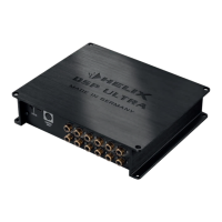
12
Line Output
12-channel pre-amplier output for connecting
po wer ampliers. The output voltage is 8 Volts
max. Please make sure that you always turn on /
o external ampliers using the remote output of
the signal processors Power Input. Never direct-
ly control the external amps by a signal from the
ignition switch of your car! Additionally this output
will be turned o when the “Power Save Mode” of
the signal processor is active. The outputs can be
assigned to any of the inputs as desired using the
DSP PC-Tool software.
 Loading...