12
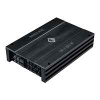
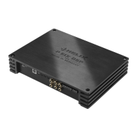
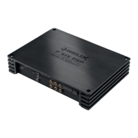
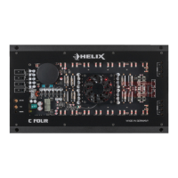
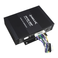
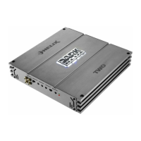
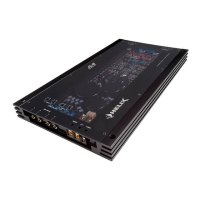
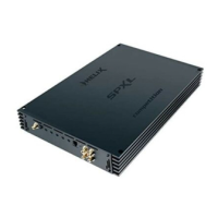
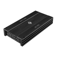
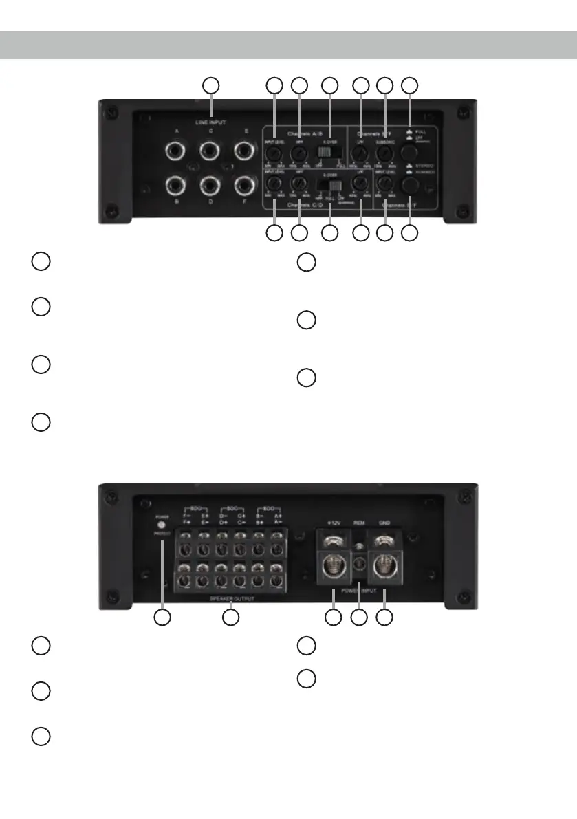
Connectors and control units
8
Power & Protect LED
This LED indicates the operating mode of the
amplier.
9
Speaker Output
Speaker outputs for connecting speaker
systems.
10
+12 V
Connector for the +12 V power cable of the
positive terminal of the battery.
11
REM
Connector for the remote cable.
12
GND
Connector for the ground cable (negative
terminal of the battery or metal body of the
vehicle).
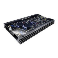
1
Line Input
RCA inputs for connecting lowlevel line
signals.
2
Input Level
Control for adjusting the input sensitivity of
the lowlevel Line Inputs for the individual ste-
reo signals.
3
HPF
Control for adjusting the highpass lter of
the channel pairs A/B and C/D from 15 Hz to
4,000 Hz.
4
X-Over
Switch for activating the lters for each
channel pair.
5
LPF
Control for adjusting the lowpass lter of the
channel pairs C/D and E/F from 40 Hz to
4,000 Hz.
6
Subsonic / HPF
Control for adjusting the subsonic / high-
pass lter of the channel pair E/F from 15 to
4,000 Hz.
7
Input Mode channel E/F
Switch to summate the input signals of
the channels E and F and to route it to the
respective amplier channels.
9 10 11 128
1 2 53 4 6
3 4 5 22
4
7
 Loading...