13
Initial start-up and functions
1
Line Input
6-channel lowlevel line input to connect signal
sourc es such as head units / radios / DSPs.
2
Input Level
These controls are used to adapt the input sensi-
tivity of the channel pairs A/B, C/D and E/F to the
output voltage of the connected signal source.
This is not a volume control, it´s only for adjusting
the amplier gain. The control range is 0.5 - 6 Volts.
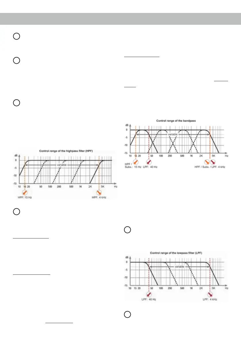
3
HPF
This control is used to adjust the crossover
frequency of the highpass lter of the channel pairs
A/B and C/D from 15 Hz to 4,000 Hz. This control is
activated if the X-Over switch of the specic chan-
nel pair is set to HPF (highpass lter). On channel
pair C/D it is also activated in switch position LPF /
Bandpass, means that its adjustment is mandatory.
4
X-Over
This switch allows to set the internal crossover to
highpass, fullrange or lowpass / bandpass mode.
The lter options depend on the channel pair.
Channel pair A/B: Highpass lter or fullrange.
If this X-Over switch is set to HPF (highpass lter)
the crossover frequency for the highpass can be ad-
justed with control 3 of the channel pair A/B.
At switch position FULL (fullrange) the crossover is
bypassed.
Channel pair C/D: Highpass lter, fullrange or low-
pass lter / bandpass.
If this X-Over switch is set to HPF (highpass lter)
the crossover frequency for the highpass can be
adjusted with control 3 of the channel pair C/D. At
switch position FULL (fullrange) the crossover is
bypassed.
At switch position LPF (lowpass lter / bandpass)
the highpass is always active. That means a band-
pass is created in any case.
By adjusting the highpass (control 3) and lowpass
lter (control 5 of the channel pair C/D) any band-
pass between 15 Hz and 4,000 Hz can be realized.
Channel pair E/F: Fullrange or lowpass lter / band-
pass.
At switch position FULL (fullrange) the crossover is
bypassed. If this switch is set to LPF (lowpass lter /
bandpass) the subsonic / highpass lter is always
active. That means a bandpass is created in any
case.
By adjusting the subsonic / highpass (control 6) and
lowpass lter (control 5 of the channel pair E/F) any
bandpass between 15 Hz and 4,000 Hz can be re-
alized.
Caution: To avoid a loss of gain make sure that the
crossover frequencies of the highpass or subsonic /
HPF and lowpass lters do have an interval of at
least two octaves when generating a bandpass.
That means if the lowpass signal is adjusted to
320 Hz the highpass or subsonic / HPF should be
adjusted to 80 Hz or less (one octave = doubled fre-
quency or halved frequency).
5
LPF
This control is used to adjust the crossover frequen-
cy of the lowpass lter of the channel pairs C/D and
E/F from 40 Hz to 4,000 Hz.
6
Subsonic / HPF
This control is used to adjust the crossover frequen-
cy of the subsonic / highpass lter of the channel
 Loading...