Page 7For technical questions, please call 1-888-866-5797.Item 59615
SETUP - BEFORE USE
Read the ENTIRE IMPORTANT SAFETY
INFORMATION section at the beginning of
this manual including all text under
subheadings therein before set up or use
.
TO PREVENT SERIOUS INJURY FROM ACCIDENTAL
OPERATION: Turn Power “OFF” and remove the
Battery Pack before performing any procedure in
this section.
Assembly
Edge Guide Installation
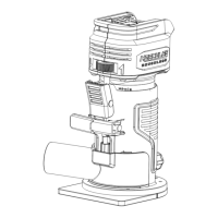
1. Assemble the Edge Guide using the locking screw
and wing nut with its washer and lock washer.
Guide Bracket
Edge Guide
Locking Screw
Washer
Wing Nut
Lock Washer
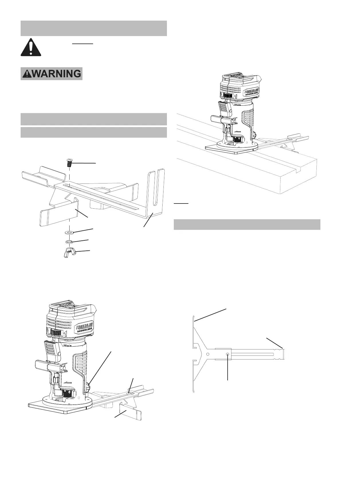
2. Loosen the Guide Locking Knob. The short
end of the Edge Guide should slide underneath
the Guide Locking Knob. Align the Edge Guide
to the mounting position of the Base Plate
and insert it to the desired working height.
Guide
Locking Knob
Edge Guide
Edge Guide
Depth Adjustment
3. Secure the Edge Guide in position by tightening
the Guide Locking Knob clockwise.
4. To adjust the Edge Guide:
a. Loosen the Edge Guide Wing
Nut counterclockwise.
b. Slide the Edge Guide to desired working position.
c. Retighten the Wing Nut to secure the Edge Guide.
5. Align the Edge Guide along the material to be
routed to cut parallel with the workpiece edge.
Note: The Edge Guide may be used for circle
cutting by turning the Edge Guide over and using the
center gap in the Edge Guide to follow the circle.
Temporary Guide Installation
A temporary guide can be used to make a straight cut
which does not parallel the edge of the workpiece.
1. Clamp a suitable straight board across the workpiece
parallel to the desired location of the cut.
2. Install the Edge Guide Assembly with the
Edge Guide facing outward and up. The Wing
Nut should be installed in the hole furthest
from the raised edge of the Edge Guide.
Raised Edge of Parallel Guide
(Outward and Up)
Attach Wing Nut
Raised Edge of
Parallel Guide Bracket
(Attached to Router)